FIBER OPTIC COLLIMATORS

Fiber collimator is an effective passive optical component used for laser beam collimating. and Fiber optic collimators come in many forms.

Fiber collimator is an effective passive optical component used for laser beam collimating. and Fiber optic collimators come in many forms.

There are more things to consider  when it comes to purchasing collimators .

  • LENS TYPE
  • SIZE DOES MATTER
  • SPHERICAL OR CHROMATIC ABERRATION
  • SINGLEMODE OR MULTIMODE
  • PAIRING, TARGETING, OR LASER PIGTAILING
  • 0 DEGREE OR 8 DEGREE
  • ALTERNATIVES


Introduction to Fiber Collimator

Fiber Optic Collimators are devices used to expand and collimate the output light at the fiber end, or to couple light beams between two fibers. They are a module that combine a fiber and a lens, and has a function that produces parallel beams. We offer a range of fixed and adjustable fiber optic collimation packages for collimating a laser beam from the end of an FC/APC, FC/PC, or SMA connectorized fiber while maintaining diffraction-limited performance at the design wavelength.  They are available with different wavelengths (850 nm, 980 nm, 1060 nm, 1310 nm, 1550 nm) or fiber options (SM fiber, MM fiber, PM fiber, and LMA fiber, etc).

A fiber collimator is a device that narrows a beam of particles or waves. It can either cause the directions of light to become more aligned in a specific direction, or cause the spatial cross section of the beam to become smaller. Usually, fiber collimator is required to naturally transform diverging lights from an optical fiber to a parallel beam of light. It consists a single-mode or multimode fiber pigtail and a collimating lens. Collimator can also be used to calibrate other optical devices to check if all elements are aligned on the optical axis.

6e771d4efc41234527a8c1675ff5c3b3.image.500x500.jpg

Characteristics

  • Low Insertion Loss and Return Loss
  • Low Back Reflection
  • High Extinction Ratio
  • Low Insertion Loss
  • Wide Operating Wavelength and Temperature
  • Scientific design with serious processing art


Applications

  • Optical cable jumper or pigtail cable
  • Laser Beam Collimating
  • Optical cable jumper or pigtail cable
  • PM Isolator and PW WDM
  • Laser Beam Collimating


How Does It Work?

When placing the fiber end on the collimator lens, the light will be aligned to a parallel direction. Then through a slight adjustment of fiber end position, the working distance is obtained. The working distance of fiber collimator is related to the distance between fiber end and lens. According to the actual demands, we can determine the parameters of fiber collimator, such as distance between fiber end and lens, beam radius, accuracy, to achieve better performance.

diffractive-collimator-layout.png

Conclusion

Selecting the right type of fiber collimator is essential to the performance of network, you should consider your project requirements as important factors. Fiber-MART offer a range of fixed and adjustable fiber optic collimation packages for collimating a laser beam from the end of an FC/APC, FC/PC, or SMA connectorized fiber while maintaining diffraction-limited performance at the design wavelength. For more information, welcome to visit www.fiber-mart.com or contact me by E-mail: service@fiber-mart.com 

How to Use OADM in WDM Network ?

OADM is a cost-effective and easy to use passive fiber optic component, which can provide easy to build and grow connectivity environment for WDM network.

OADM is a cost-effective and easy to use passive fiber optic component, which can provide easy to build and grow connectivity environment for WDM network.Optical add-drop multiplexer is one of the key devices to implement such optical signal processing. Use of OADM makes it possible to freely add or drop signals with arbitrary wavelengths over multiplexed optical signals by assigning a wavelength to each destination.this article ,Let us introduce how to use OADM in WDM Network?

Inside an OADM

A traditional OADM consists of three parts: an optical demultiplexer, an optical multiplexer and between them a method of reconfiguring the paths between the optical demultiplexer, the optical multiplexer and a set of ports for adding and dropping signals. The multiplexer is used to couple two or more wavelengths into the same fiber. Then the reconfiguration can be achieved by a fiber patch panel or by optical switches which direct the wavelengths to the optical multiplexer or to drop ports. The demultiplexer undoes what the multiplexer has done. It separates a multiplicity of wavelengths in a fiber and directs them to many fibers.

7c9546ae7ce1e487020af173dcd323e4.image.500x500.jpg

Main Function and Principle of OADM

For an OADM, “Add” refers to the capability of the device to add one or more new wavelength channels to an existing multi-wavelength WDM signal while “drop” refers to drop or remove one or more channels, passing those signals to another network path. The OADM selectively removes (drops) a wavelength from a multiplicity of wavelengths in a fiber, and thus from traffic on the particular channel. It then adds in the same direction of data flow the same wavelength, but with different data content. The main function of OADM function is shown in the following picture. This function is especially used in WDM ring systems as well as in long-haul with drop-add features.

How to Connect OADM With WDM MUX/DEMUX

In most cases, OADM is deployed with CWDM or DWDM MUX/DEMUX. It is usually installed in a fiber optic link between two WDM MUX/DEMUXs. The following picture shows a CWDM network using a 1-channel dual fiber OADM between two CWDM MUX/DEMUXs. Signals over 1470 nm are required to be added to and dropped from the dual fiber link. On the OADM, there are usually one port for input and one port for output. The OADM can be regarded as a length of fiber cable in the fiber link. The point is the one or more strand of signals is added or dropped when the light goes through the OADM.

OADM-Technology.jpg

Summary

OADM is still evolving, and although these components are relatively small, they are immeasurable in the future.Optical Add-Drop Multiplexer (OADM) is used for multiplexing and routing different channels of fiber into or out of a single fiber. The CWDM OADM is designed to optically add/drop one or multiple CWDM channels into one or two fibers. Fiber-Mart provides a series of OADM modules which can be Customized. For more information, welcome to visit www.fiber-mart.com or contact me by e-mail: service@fiber-mart.com

How to Place EDFA for DWDM Distance Extension?

No matter where the EDFA optical amplifier is deployed in the DWDM link, the signal power can be always enhanced for making a longer DWDM system.Undoubtedly, the EDFA amplifier is an ideal choice for long-haul DWDM system. But how does it work for extending DWDM system?

No matter where the EDFA optical amplifier is deployed in the DWDM link, the signal power can be always enhanced for making a longer DWDM system.Undoubtedly, the EDFA amplifier is an ideal choice for long-haul DWDM system. But how does it work for extending DWDM system?

Optic Amplifier Basics

The basic form of EDFA consists of a length of EDFA, a pump laser, and a WDM system for combining the signal and pump wavelength so that they can propagate simultaneously through the EDF.

When transmitting over long distance, the optical signal has to be amplified many times in between owing to the signal loss from fiber attenuation, connectivity losses, fiber splicing losses, etc. Before optical amplifier is invented, the optical signal has to be first converted into electrical signal, amplified, and then converted back to optical signal again. The process is very complicated and expensive. Optical amplifier has since been invented that can amplify signals directly, this process is significantly cheaper and started a fiber optic revolution. There are three fiber optic amplifier types: EDFA, Raman amplifier and semiconductor optical amplifier(SOA).

EDFA (Erbium Doped Fiber Amplifier) principle

EDFAs use a pump laser (980 nm or 1480 nm) to bring up electrons to a higher energy level. If signal amplification is achieved by emitted photons of the same signal wavelength with the help of stimulated emission.

图片1.png


An erbium-doped fiber amplifier (EDFA) is a device that amplifies an optical fiber signal. It is used in the telecommunications field and in various types of research fields. An EDFA is “doped” with a material called erbium. The term “doping” refers to the process of using chemical elements to facilitate results through the manipulation of electrons.The EDFA was the first successful optical amplifier and a significant factor in the rapid deployment of fiber optic networks during the 1990s.

The EDFA rate, or amplification window, is based on the optical wavelength range of amplification and is determined by the dopant ions’ spectroscopic properties, the optical fiber glass structure and the pump laser wavelength and power. As ions are sent into the optical fiber glass, energy levels broaden, which results in amplification window broadening and a light spectrum with a broad gain bandwidth of fiber optic amplifiers used for wavelength division multiplex communications. This single amplifier may be used with all optic fiber channel signals when signal wavelengths are in the amplification window. Optical isolator devices are placed on either side of the EDFA and serve as diodes, which prevent signals from traveling in more than one direction.

How Does EDFA Amplifier Work?

Placed at the Transmitting Side : A booster optical amplifier operates at the transmission side of the link, working to amplify aggregated optical input power for reach extension. Booster EDFA is designed to enhance the transmitted power level or to compensate for the losses of optical elements between the laser and optical fibers. It is usually adopted in a DWDM network where the multiplexer attenuates the signal channels. Booster optical amplifier features high input power, high output power, and medium optical gain.

 2-1.png


Placed at the Intermediate Points: as shown in the figure below, the EDFA in-line amplifier can be put at any intermediate point along the long transmission link. This kind of EDFA optical amplifier is designed with low input power, high output power, high optical gain and low noise figure, which are normally deployed every 80-100 km to amplify signals between any two link nodes on the main optical link, with the aim of compensating the loss caused by fiber transmission and other factors. Thereby, the optical signal level can stay above the noise floor.


2-2


Placed at the Receiving Side: A pre-amplifier operates at the receiving end of a DWDM link. Pre-amplifiers are used for optical amplification to compensate for losses in a demultiplexer located near the optical receiver. Placed before the receiver end of the DWDM link, pre-amplifier works to enhance the signal level before the photo detection takes place in an ultra-long haul system, hence improving the receive sensitivity. It features medium to low input power, medium output power, and medium gain.


2-3.png


Conclusion

The EDFA optical amplifier can be deployed as booster optical amplifier , in-line amplifier and pre-amplifier contributes to optimize network performance for extending the reach. It can also work as in-line amplifier at the intermediate point along the link for compensating the fiber loss in the transmission link.Which also increases data capacity required for current and future optical communication system. Optical Amplifiers provided by Fiber-Mart are designed for all network segments (access, metro, regional and long haul) and applications (telecom, cable and enterprise). any question pls not hesitate to contact us www.fiber-mart.com or E-mail: service@fiber-mart.com

Introduction to Passive Optical Network (PON)

Seen from the entire network structures,the Passive Optical Network (PON) market is in a high-growth period due to the ongoing deployments of Fiber to the Home (FTTH) networks

Seen from the entire network structures,the Passive Optical Network (PON) market is in a high-growth period due to the ongoing deployments of Fiber to the Home (FTTH) networks.today, we mainly Introduce Passive Optical Network (PON).

What does Passive Optical Network (PON)mean?

A passive optical network (PON) is a cabling system that uses optical fibers and optical splitters to deliver services to multiple access points. A PON system can be fiber-to-the-curb (FTTC), fiber-to-the-building (FTTB) or fiber-to-the-home (FTTH). A PON system consists of optical line termination (OLT) at the communication provider’s end and a number of optical network units (ONUs) at the user’s end. The term “passive” simply means that there are no power requirements while the network is up and running.


A PON consists of an optical line terminal (OLT) at the service provider’s central office (hub) and a number of optical network units (ONUs) or optical network terminals (ONTs), near end users. A PON reduces the amount of fiber and central office equipment required compared with point-to-point architectures. A passive optical network is a form of fiber-optic access network.In most cases, downstream signals are broadcast to all premises sharing multiple fibers. Encryption can prevent eavesdropping.upstream signals are combined using a multiple access protocol, usually time division multiple access (TDMA).

What is PON 2.jpg.png


Feature

A PON takes advantage of wavelength division multiplexing (WDM), using one wavelength for downstream traffic and another for upstream traffic on a single mode fiber (ITU-T G.652). BPON, EPON, GEPON, and GPON have the same basic wavelength plan and use the 1490 nanometer (nm) wavelength for downstream traffic and 1310 nm wavelength for upstream traffic. most common is 28 dB of loss budget for both BPON and GPON, but products have been announced using less expensive optics as well. 28 dB corresponds to about 20 km with a 32-way split. Forward error correction (FEC) may provide for another 2–3 dB of loss budget on GPON systems. As optics improve, the 28 dB budget will likely increase. Although both the GPON and EPON protocols permit large split ratios (up to 128 subscribers for GPON, up to 32,768 for EPON), in practice most PONs are deployed with a split ratio of 1:32 or smaller.

A PON consists of a central office node, called an optical line terminal (OLT), one or more user nodes, called optical network units (ONUs) or optical network terminals (ONTs), and the fibers and splitters between them, called the optical distribution network (ODN). “ONT” is an ITU-T term to describe a single-tenant ONU. In multiple-tenant units, the ONU may be bridged to a customer premises device within the individual dwelling unit using technologies such as Ethernet over twisted pair, G.hn (a high-speed ITU-T standard that can operate over any existing home wiring – power lines, phone lines and coaxial cables) or DSL. An ONU is a device that terminates the PON and presents customer service interfaces to the user. Some ONUs implement a separate subscriber unit to provide services such as telephony, Ethernet data, or video.

An OLT provides the interface between a PON and a service provider′s core network. These typically include:

  • IP traffic over Fast Ethernet, gigabit Ethernet, or 10 Gigabit Ethernet;
  • Standard TDM interfaces such as SDH/SONET;
  • ATM UNI at 155–622 Mbit/s.

functions are separated into two parts:

  • The ONU, which terminates the PON and presents a converged interface—such as DSL, coaxial cable, or multiservice Ethernet—toward the user;
  • Network termination equipment (NTE), which inputs the converged interface and outputs native service interfaces to the user, such as Ethernet and POTS.


The Benefits of PON

As early as before, PONs began appearing in corporate networks. Users were adopting these networks because they were cheaper, faster, lower in power consumption, easier to provision for voice, data and video, and easier to manage, since they were originally designed to connect millions of homes for telephone, Internet and TV services.Passive Optical Networks (PON) provide high-speed, high-bandwidth and secure voice, video and data service delivery over a combined fiber network.

The main benefits of PON as below:

  • Lower network operational costs
  • Elimination of Ethernet switches in the network
  • Elimination of recurring costs associated with a fabric of Ethernet switches in the network
  • Lower installation (CapEx) costs for a new or upgraded network (min 200 users)
  • Lower network energy (OpEx) costs
  • Less network infrastructure
  • You can reclaim wiring closet (IDF) real estate
  • Large bundles of copper cable are replaced with small single mode optical fiber cable
  • PON provides increased distance between data center and desktop (>20 kilometers)
  • Network maintenance is easier and less expensive


Conclusion

According to the above article, you may have a understanding of the passive optical network.A PON network eliminates the need for switches and a wiring closet, which means fewer points of failure. Fiber-Mart manufactures and offers customized services. any question pls welcome to visit www.fiber-mart.com or contact us.E-mail: service@fiber-mart.com

EPON VS GPON

As the infrastructure for access networks, fiber is making rapid headway in the world’s leading technology markets.

As the infrastructure for access networks, fiber is making rapid headway in the world’s leading technology markets. With passive optical networking (PON) technology gaining popularity, Ethernet passive optical networking (EPON) and igabit passive optical network (GPON) are both in active deployment.

What’s the EPON?

EPON (Ethernet PON) generally delivers 1 Gbit/s symmetrical bandwidth.And its Gigabit Ethernet service actually constitutes 1 Gbit/s of bandwidth for data and 250 Mbit/s of bandwidth for encoding.Employs a single Layer 2 network that uses Internet Protocol (IP) to carry data, voice, and video, generally delivers 1 Gbit/s symmetrical bandwidth.

EPON is a device which serves as the service provider endpoint of apassive optical network. to perform conversion between the electrical signals used by the service provider’s equipment and the fiber optic passive component signals used by the passive optical network. To coordinate the multiplexing between the conversion devices on the other end of that network (called either optical network terminals or optical network units).

What’s the GPON?

GPON, FSAN and ITU have standardized it. Its technical feature is to use ITU-T-defined GFP (General framing procedure) to encapsulate and map multiple services such as Ethernet, TDM and ATM at the second layer, which can provide 1.25Gbps and 2.5Gbps downlink rate, and 155M, 622M, 1.25Gbps, 2.5Gbps several uplink rates, and has a strong OAM function. If you don’t consider EPON, you will see that it will increase to 10Gbps (10G Ethernet is mature). Currently, GPON has advantages in high-speed and multi-service support, but the complexity and cost of technology are currently higher than EPON.


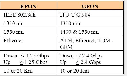
Comparison of EPON and GPON


GPON and EPON Differences

Perhaps the most dramatic distinction between the two protocols is a marked difference in architectural approach. GPON provides three Layer 2 networks: ATM for voice, Ethernet for data, and proprietary encapsulation for voice. EPON, on the other hand, employs a single Layer 2 network that uses IP to carry data, voice, and video.

图片1.png

GPON vs EPON: Data Rate

EPON, based on a 10-Gbit/s Ethernet version designated 802.3av. The actual line rate is 10.3125 Gbits/s. The primary mode is 10 Gbits/s upstream as well as downstream. A variation uses 10 Gbits/s downstream and 1 Gbit/s upstream. The 10-Gbit/s versions use different optical wavelengths on the fiber, 1575 to 1580 nm downstream and 1260 to 1280 nm upstream so the 10-Gbit/s system can be wavelength multiplexed on the same fiber as a standard 1-Gbit/s system.

GPON, based on the GPON packets can handle ATM packets directly. Recall that ATM packages everything in 53-byte packets with 48 for data and 5 for overhead. GPON also uses a generic encapsulation method to carry other protocols. It can encapsulate Ethernet, IP, TCP, UDP, T1/E1, video, VoIP, or other protocols as called for by the data transmission. Minimum packet size is 53 bytes, and the maximum is 1518. AES encryption is used downstream only.

Conclusion: GPON is better than EPON


Technology Comparison

EPON, based on Ethernet is the best carrier for carrying IP services; it is easy to maintain, easy to expand, easy to upgrade; EPON equipment is mature and available, EPON has already laid millions of lines in Asia, third-generation commercial chips have been introduced, related optical modules, chip prices Both have dropped significantly, reached the scale of commercial level, and can meet the requirements of recent broadband services; EPON protocol is simple and low in implementation cost, equipment cost is low, and the most suitable technology is needed in the metro access network, not the best technology.

GPON, based on Access network for telecom operation; high bandwidth: line rate, downlink 2.488Gb/s, uplink 1.244Gb/s; high transmission efficiency: 94% (actual bandwidth up to 2.4G) behavior 93% (actual bandwidth up to 1.1) G); business support: G.984.X standard strictly defines the support of carrier-class full service (voice, data and video); strong management capabilities: rich in features, reserved sufficient OAM domain in the frame structure, and The OMCI standard has been developed; the service quality is high: multiple QoS levels can strictly guarantee the bandwidth and delay requirements of the service; the comprehensive cost is low: the transmission distance is long, the split ratio is high, the OLT cost is effectively allocated, and the user access cost is reduced.

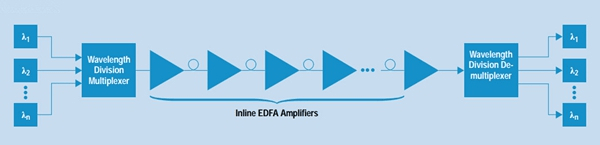
Conclusion: As the parts of PON, they have something in common. For example, they both can be accepted as international standards, cover the same network topology methods and FTTx applications, and use WDM (wavelength-division multiplexing) with the same optical frequencies as each other with a third party wavelength; and provide triple-play, Internet Protocol TV (IPTV) and cable TV (CATV) video services

Costs Comparison

PON, as a FTTH technology, is an ideal solution to deliver last-mile broadband access. The optical line terminal (OLT), optical network unit (ONU) and optical distribution network (ODN), which comprise a PON system, decide the costs of GPON and EPON deployments.

The cost of OLT and ONT is influenced by the ASIC (application specific integrated circuit) and optic module. Recently, the chipsets of GPON are mostly based on FPGA (field-programmable gate array), which is more expensive than the EPON MAC layer ASIC. On the other hand, the optic module’s price of GPON is also higher than EPON’s. When GPON reaches deployment stage, the estimated cost of a GPON OLT is 1.5 to 2 times higher than an EPON OLT, and the estimated cost of a GPON ONT will be 1.2 to 1.5 times higher than an EPON ONT.

Conclusion: the cost of EPON and GPON would be the same.


Summary

Currently, we are still unclear whether EPON or GPON will prevail. EPON and GPON have their own advantages and disadvantages. But one thing is clear: PON system is undoubtedly one of the best, EPON and GPON, both technologies have their own advantages, whether it is EPON technology or GPON technology, its application is largely determined by the rapid reduction of fiber access costs and business needs. For more information,welcome to visit www.fiber-mart.com or contact us service@fiber-mart.com

WHAT IS OPTICAL CIRCULATOR ?

With the development of advanced optical networks, applications of optical circulators are expanding rapidly and new functionality and applications are emerging quickly.

With the development of advanced optical networks, applications of optical circulators are expanding rapidly and new functionality and applications are emerging quickly. Because of its high isolation of the input and reflected optical powers and its low insertion loss, optical circulators are widely used in advanced communication systems and fiber-optic sensor applications.

What is Optical Circulator?

An optical Circulator is a non reciprocal device allowing for the Routing of Light from one Fiberto another based upon the direction of the light propagation.

Optical circulators enable the routing of light from one Optical Fiber or Waveguide to another based upon the direction of light propagation. A circulator has at least three optical ports. These ports can be accessed in such order that when a light beam is caused to enter into an optical port, this light-beam after passing through the circulator to exit from a next optical port. The light enters the circulator through a first Port and exits through a second port. Another light that enters the second port exits through a third port and so on. Since the optical circulator is an inherently non-reciprocal device, the light never goes to other ports. Optical Circulator is a passive optical component that can be used to achieve bi-directional transmission over a single fiber in WDM optical networks. It is widely implemented in equipment such as Dispersion Compensation Modules (DCMs), Optical Add-Drop Multiplexers (OADMs), Optical Time-Domain Reflectometers (OTDRs), optical amplifiers, and fiber optic sensors.


Principle of Optical Circulator

Fiber optic circulators are non-reciprocal optics, which means that changes in the properties of light passing through the device are not reversed when the light passes through in the opposite direction.a special fiber-optic component that can be used to separate optical signals that travel in opposite directions in an optical fiber, analogous to the operation of an electronic circulator. An optical circulator is a three-port device designed such that light entering any port exits from the next. This means that if light enters port 1 it is emitted from port 2, but if some of the emitted light is reflected back to the circulator, it does not come out of port 1, but instead exits from port 3.

22.png

Applications of Optical Circulator

Optical circulator can be utilized to achieve bi-directional optical signal transmission over a single fiber. It is a very important optical component which is commonly used in passive optical network, (wavelength division multiplexing) WDM network, polarization mode dispersion, chromatic dispersion compensation, optical add-drop modules (OADM), optical amplifiers, optical time domain reflectometry (OTDR) and fiber sensing applications. Fiber-Mart provides both polarization insensitive and polarization maintaining optical circulators. These optical circulators feature with high isolation, low insertion loss, and excellent environmental stability etc. Customers can buy these circulators directly in this category or Make Customized Orders.


Main Features of Optical Circulator

  • High isolation
  • Low insertion loss
  • Low polarization dependent loss
  • Low polarization mode dispersion
  • Excellent environmental stability


From this article,you may have a certain understanding of the optical circulator. for more detailed information about optical circulator, welcome to visit www.fiber-mart.com or contact us :Service@fiber-mart.com