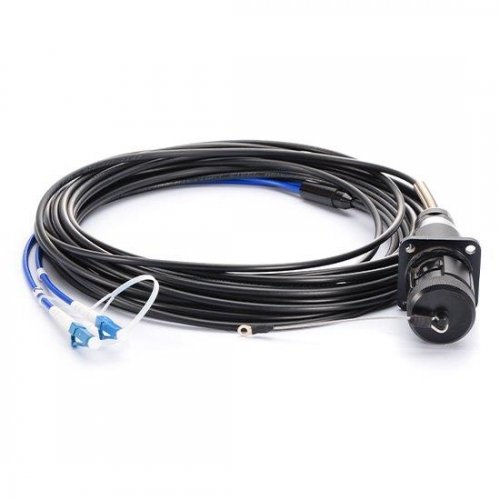
What is Fiber Optic Adapter?
Fiber optic adapters (also known as Fiber couplers, Fiber Adapter ) are designed to connect two optic cables together. They have a single fiber connector (simplex), dual fiber connector (duplex) or sometimes four fiber connector (quad) versions. The optical fiber adapter can be inserted into different types of optical connectors at both ends of the optical fiber adapter to realize the conversion between different interfaces such as FC, SC, ST, LC, MTRJ, MPO and E2000, and is widely used in optical fiber distribution frames (ODFs) Instruments, providing superior, stable and reliable performance.
Features of Fiber Optic Adapter
The optical fibers are connected by an adapter through its internal open bushing to ensure the maximum connection between the optical connectors. In order to be fixed in a variety of panels, the industry also designed a variety of finely fixed flange.
Transformable optical adapters are available with fiber optic connectors of different interface types on both ends and provide a connection between APC faceplates. Duplex or multi-adapter adapts to increase installation density and save space.
Fiber Optic Adapter types
FC Fiber Optic Adapter
This fiber optic adapter was first developed by Japan NTT. FC is an acronym for FERRULE CONNECTOR, indicating that its external reinforcement is the use of the metal sleeve, fastening the way for the buckle. The earliest, FC type connector, the docking end of the ceramic pin. Such connectors are simple in structure, easy to operate and easy to manufacture. However, the fiber end face is more sensitive to dust, and it is easy to produce Fresnel reflection and it is difficult to improve the return loss performance. Later, this type of connector has been improved, the use of docking the spherical end of the pin (PC), while the external structure has not changed, making the insertion loss and return loss performance has been greatly improved.
SC Fiber Optic Adapter
This is a kind of optical fiber connector developed by Japan NTT Corporation. The shell is rectangular, the pin and the coupling sleeve used in the structure of the same size and FC type. One end of the pin to use more PC or APC grinding method; fastening method is the use of plug pin type, without rotation. Such connectors are inexpensive, easy to plug and unplug, low insertion loss variations, high compressive strength, and high installation density.
DIN47256 Fiber Optic Adapter
This is a connector developed by Germany. The pins and coupling sleeves used in this connector are the same size as the FC type and the PC process is used for the end face processing. Compared with the FC type connector, the structure is more complex, and the internal metal structure has a control pressure spring to prevent the end face from being damaged due to the excessive insertion pressure. In addition, this connector has higher mechanical accuracy and therefore smaller insertion loss values.
MT-RJ Fiber Optic Adapter
MT-RJ started with the MT connector developed by NTT with the same latching mechanism as the RJ-45 type LAN electrical connector. Alignment of the optical fiber with guide pins mounted on both sides of the small bushing made it easy to communicate with the optical transceiver Machine connected to the connector end of the optical fiber for the dual core (0.75MM spacing) array design is mainly used for data transmission next generation high-density fiber optic connectors.
LC Fiber Optic Adapter
The lc-type connector is a well-known BELL (Bell) Institute of research and development, the use of convenient modular jack (RJ) latch mechanism made. The pins and sleeves used are half the sizes used for normal SC, FC, etc., at 1.25mm. This will increase the density of fiber optic connectors in fiber distribution frames. Currently, in the single-mode SFF, LC type of connector has actually occupied the dominant position, the application of multi-mode is also growing rapidly.
MU Fiber Optic Adapter
The MINIATURE UNIT COUPLING connector is the world’s smallest single-core fiber optic connector developed by NTT based on the currently used SC-type connector. The connector uses a 1.25MM diameter sleeve and self-holding mechanism, the advantage is that it can achieve high-density installation. NTT has developed the MU connector family with MU’s L.25MM diameter bushings. They have socket type connectors for optical cable connections; backplane connectors with the self-holding mechanism and simplified sockets for connecting LD / PD modules and plugs Wait. Demand for MU-type connectors will also grow rapidly as fiber-optic networks become more capable of larger bandwidths and DWDM technologies are widely used.
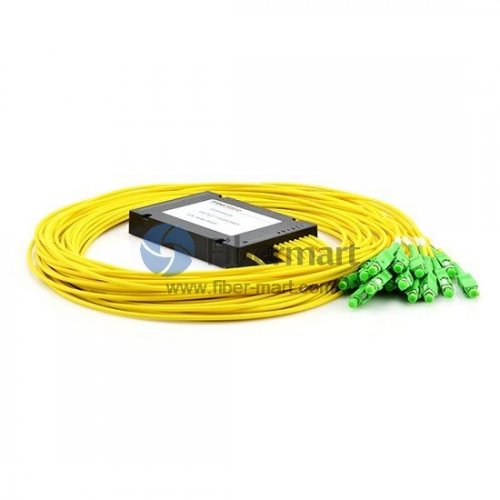
MTP/MPO Fiber Optic Adapters
Unlike the single-core SC fiber optic adapters, the SC fiber optic adapters are internally equipped with a ceramic ferrule that is precisely aligned through the ferrule when the SC connector ferrule is connected, while the MPO / MTP adapter is connected using an MPO / MTP Precise connection of two guide holes with a diameter of 0.7mm and a guide pin on the left and right ends of the ferrule. MPO / MTP adapters are widely used in communication system base stations, optical fiber distribution frames (ODFs) in building rooms, MPO / MTP cassette module, and various test instruments.