Knowledge about fiber media converter that you should know

by http://www.fiber-mart.com

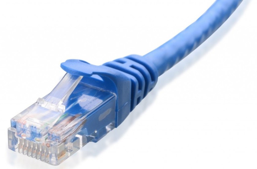
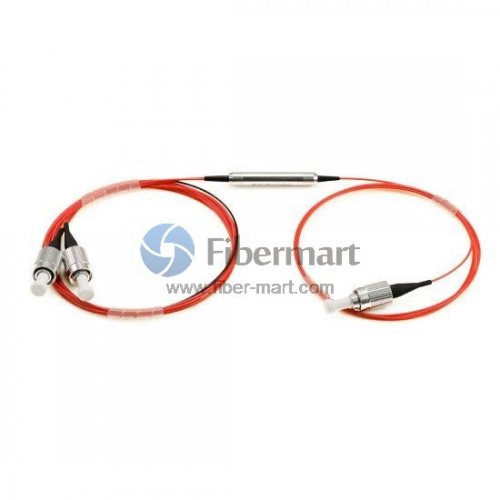
Fiber media converters include three basic functional modules: optical media conversion chip, optical signal interface (optical media converter module) and electrical interface (RJ45), if equipped with network management functions, including network management information processing unit. It is an Ethernet transmission Media conversion module that converts short distance twisted-pair signals and long distance optical signals to each other and is also called a fiber converter or Ethernet media converter. It generally applies to Ethernet cables that cannot be covered, it is necessary to use optical fiber to extend the actual network environment of transmission distance, and it is usually positioned in the access layer of broadband Metropolitan Area Network, and it also plays an important role in helping to connect the last kilometre of fiber line to the metropolitan area Network.
In some large-scale enterprises, the network construction directly using fiber for the transmission medium to establish the backbone network, and the internal LAN transmission medium is generally copper, how to achieve LAN connected with the fiber backbone network? This requires different ports, different Linear, different fiber between the conversion and to ensure the quality of the link.  The emergence of fiber-optic media converter, allows the twisted pair of electrical signals and optical signals to each other to ensure the smooth transmission of packets between the two networks while extending the network transmission distance from the copper wire from 100 meters to more than 160 kilometers (Single-mode fiber).
What are the basic features of a fiber media converter?
Fully transparent to the network protocol.
Provide ultra low delay data transmission.
Supports Ultra wide working temperature range.
Using ASIC chip to achieve data line speed forwarding. The programmable ASIC centralizes many functions on a chip, which has the advantages of simple design, high reliability, and low power consumption so that the equipment can get higher performance and lower cost.
Provide network management equipment to diagnose, upgrade, status report, abnormal Situation Report, and control function, can provide complete operation log and alarm log.
Rack-type equipment can provide hot-swappable functions for easy maintenance and uninterrupted upgrades.
Supports a variety of transmission distances (0~160 km).
The Media Converter Rack adopts the dual power supply design, supports the ultra wide power supply voltage, realizes the power protection.
What kinds of fiber media converters are available?
There is a wide range of fiber optic media converters that can be categorized in different ways.
According to the properties of an optical fiber can be divided into Multimode fiber media converter and Single-mode fiber media converter. Because of the use of different fiber, media converter can transmit the distance is not the same, Multimode fiber media converter general transmit distance between 0.5 km to 2 kilometers, and the single mode fiber media converter coverage can range from 20 km to 120 kilometers;
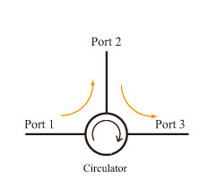
According to the number of optical fiber required can be divided into Single fiber (WDM) optic media converter, receiving data sent in a single strand fiber transmission; Dual Fiber optic media converter, receiving sent data on a pair of optical fiber transmission.
According to the work level/rate, can be divided into single 10M, 100M fiber media converter, 10/100M adaptive Fiber media converter, and 1000M fiber media converter.
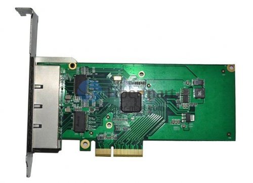
According to the structure, can be divided into desktop (stand-alone) fiber media converter and card-type optical media converter. Stand-alone fiber media converter Suitable for a single user, such as a single switch in the corridor to meet the upper allied. Card-type (modular) optical media converter suitable for multi-user convergence, such as the central room of the community must meet all the switches in the upper allied.
According to network management can be divided into management type optical media converter and non-network management type Optical media converter.
According to the power type can be divided into: internal power optical media converter, the built-in switching power supply for the telecommunications application; external power supply Optical media converter, External transformer power is used in civilian equipment. The former advantage lies in the ability to support the ultra wide power supply voltage, to better achieve voltage regulator, filter, and equipment power protection, reduce the mechanical contact caused by external fault points; the latter has the advantage that the equipment is small and inexpensive.
Divided by the way of work: Full-duplex refers to when data is sent and received streaming, by two different transmission lines, respectively, the communication between the two sides can be sent and received at the same time operation, such a transmission is full duplex system, Full-duplex mode without the direction of the switch, therefore, there is no switching operation caused by the time delay; Half-duplex refers to the use of the same transmission line both as a receiving and sending, although the data can be transmitted in two directions, the communication between the two sides can not send and receive data, such a transmission is half duplex system. In a Half-duplex mode, the transmitter and receiver of each end of the communication system are transferred to the communication line by the receiving/sending switch, and the direction is switched, thus the time delay is generated.
These are some of the basic knowledge of optical media converter, we should have a basic understanding of fiber media converter in the application before fiber cabling to avoid any trouble.

How much do you know about the RJ45 interface?

As we all know, cables can transmit information along their length. To actually get the information where it needs to go, you need to make the right connections to an RJ45 connector. Your cable run needs to terminate into a connector, which needs a jack to plug into. RJ45 is a standard type of connector for network cables, which is usually used for data transmission. RJ45 connectors are most common applications for Ethernet cables and networks.

As we all know, cables can transmit information along their length. To actually get the information where it needs to go, you need to make the right connections to an RJ45 connector. Your cable run needs to terminate into a connector, which needs a jack to plug into. RJ45 is a standard type of connector for network cables, which is usually used for data transmission. RJ45 connectors are most common applications for Ethernet cables and networks.

The RJ45 connector is a modular plug used primarily for network cabling. The connector feature eight pins to which the wire strands of a cable interface electrically. Standard RJ-45 pinouts define the arrangement of the individual wires needed when attaching connectors to a cable.

4545

RJ45 is a type of a variety of different connectors (for example: a type of RJ11 is also a connector, but it is used in the phone). The line using of RJ45 connector has two types: straight-through and cross-over.Have you ever had some confusion about RJ45 interface? That’s what we’ll explore today

Introduction of RJ45 Connector

RJ45 connector is the most common twisted-pair connector for Ethernet cables and networks. “RJ” means “registered jack”, which is a standardized telecommunication network interface for connecting voice and data equipment to a service provided by a local exchange carrier or long distance carrier. The physical connectors that registered jacks use are mainly the modular connector and 50-pin miniature ribbon connector types. RJ45 connector is an 8-position, 8-contact (8P8C) modular plug and jack, which is commonly used to connect computers onto Ethernet-based local area networks (LAN). RJ45 cable plug is usually made of a plastic piece with eight pins on the port. Four of the pins are used for sending and receiving data, and the other four are used for other technologies or power networking devices.

6645

Introduction of RJ45 Connector Color Code

As we all know, there are two wiring schemes: T568A and T568B, which are used to terminate the twisted-pair cable onto the connector interface. Two standards define how the RJ45 pinouts to arrange the individual eight wires when linking RJ45 connector to a cable. These wiring layouts have their own color convention, and following the convention is important to ensure electrical compatibility.

RJ45 Connector VS. RJ11 Connector

Several other types of connectors closely resemble RJ45, and the RJ11 connector used with telephone cables is one of such connectors. The close physical similarity of RJ45 and RJ11 makes it difficult for an untrained eye to tell the two apart. RJ11 connector is a 6P2C (6 position 2 contact) modular connector – only uses six positions rather than eight positions, which make them less popular than RJ45 connectors.

RJ45 and RJ11 are two commonly used jacks, each with their own specific purpose. The biggest difference between them is that they are used for different applications. RJ45 is used in networking, where you connect computers or other network elements to each other. RJ11 is the cable connector that is being used in telephone sets.

45

Aside from the application, another difference is the number of wires in their connectors. If you look closely at both connectors, you would see that there are only four wires inside an RJ11 while there are eight wires inside an RJ45. As a consequence, RJ45 connector is a little bit bigger than RJ11. It is then quite easy to deduce that you cannot plug in an RJ45 connector to a RJ11 slot but the opposite is possible. Although the smaller size of RJ11 makes it easier to be plugged into the RJ45 slot, it is not recommended to do so since this may damage the device that adopts the RJ45 slot. With proper knowledge and training, some people have been able to use RJ45s all over their house instead of RJ11s.

At present, RJ45 jacks are usually placed on the wall outlets inside people’s houses to reduce the number of visible wiring when using VoIP handsets that are rapidly gaining popularity.

RJ45 type network interface

10/100 Base TX RJ45 interface is commonly used in Ethernet interface, support for network connection speed of 10Base and 100Base of adaptive common RJ45 connector into two categories: for Ethernet cards, routers and Ethernet interface DTE type, for switches DCE type. DTE can be called data terminal equipment; the DCE can be called data communications equipment. In one sense, the DTE device is called the “active communications equipment DCE device called a” passive communications equipment. When the two types of devices use RJ45 interface communication, you must use a crossover cable. This can be defined from the following types of pin definitions of the RJ45 the DTE and RJ45 DCE type pin.

 RJ45 type cable plug

The RJ45 network cable connector also known as crystal head which a total of eight cores made of, widely used in LAN and ADSL broadband Internet connection to the user’s cable network equipment which named as CAT cables or twisted-pair. In the specific application, the RJ45-type plugs and cables, there are two connection methods, respectively called T568A line sequence and T568B linear order.

45454545

Application in products

RJ45 ports are available on fiber optical products like media converters, pci-e cards, PDH multiplexers, protocol converters, Patch panels, and so on.

Conclusion

RJ45 connectors are the key part of Ethernet connectivity to transmit voice and data media. They were developed as much smaller and cheaper replacements to the older telephone installation methods of hardwired cords. The easy plug-n-play style reduces the difficulty of installation. Compared with RJ11, RJ45 is suitable for more applications, such as Ethernet networking, telecommunications, factory automation and so on. It is frequently used for networking devices including Ethernet cables, modems, computers, laptops, printers, etc.


WHAT IS OPTICAL CIRCULATOR ?

With the development of advanced optical networks, applications of optical circulators are expanding rapidly and new functionality and applications are emerging quickly.

With the development of advanced optical networks, applications of optical circulators are expanding rapidly and new functionality and applications are emerging quickly. Because of its high isolation of the input and reflected optical powers and its low insertion loss, optical circulators are widely used in advanced communication systems and fiber-optic sensor applications.

What is Optical Circulator?

An optical Circulator is a non reciprocal device allowing for the Routing of Light from one Fiberto another based upon the direction of the light propagation.

Optical circulators enable the routing of light from one Optical Fiber or Waveguide to another based upon the direction of light propagation. A circulator has at least three optical ports. These ports can be accessed in such order that when a light beam is caused to enter into an optical port, this light-beam after passing through the circulator to exit from a next optical port. The light enters the circulator through a first Port and exits through a second port. Another light that enters the second port exits through a third port and so on. Since the optical circulator is an inherently non-reciprocal device, the light never goes to other ports. Optical Circulator is a passive optical component that can be used to achieve bi-directional transmission over a single fiber in WDM optical networks. It is widely implemented in equipment such as Dispersion Compensation Modules (DCMs), Optical Add-Drop Multiplexers (OADMs), Optical Time-Domain Reflectometers (OTDRs), optical amplifiers, and fiber optic sensors.


Principle of Optical Circulator

Fiber optic circulators are non-reciprocal optics, which means that changes in the properties of light passing through the device are not reversed when the light passes through in the opposite direction.a special fiber-optic component that can be used to separate optical signals that travel in opposite directions in an optical fiber, analogous to the operation of an electronic circulator. An optical circulator is a three-port device designed such that light entering any port exits from the next. This means that if light enters port 1 it is emitted from port 2, but if some of the emitted light is reflected back to the circulator, it does not come out of port 1, but instead exits from port 3.

22.png

Applications of Optical Circulator

Optical circulator can be utilized to achieve bi-directional optical signal transmission over a single fiber. It is a very important optical component which is commonly used in passive optical network, (wavelength division multiplexing) WDM network, polarization mode dispersion, chromatic dispersion compensation, optical add-drop modules (OADM), optical amplifiers, optical time domain reflectometry (OTDR) and fiber sensing applications. Fiber-Mart provides both polarization insensitive and polarization maintaining optical circulators. These optical circulators feature with high isolation, low insertion loss, and excellent environmental stability etc. Customers can buy these circulators directly in this category or Make Customized Orders.


Main Features of Optical Circulator

  • High isolation
  • Low insertion loss
  • Low polarization dependent loss
  • Low polarization mode dispersion
  • Excellent environmental stability


From this article,you may have a certain understanding of the optical circulator. for more detailed information about optical circulator, welcome to visit www.fiber-mart.com or contact us :Service@fiber-mart.com

40G & 100G Optical Transceivers Basics

by http://www.fiber-mart.com

40G and 100G have two main types in the data center. Short reach (SR4) for ~100 meters transmission on multimode fiber and Long Reach (LR4) for 100 meters to 10km using single-mode fiber. We can use SR/LR transceivers to connect compute clusters and various switches layers in data centers. 40G transceivers are typically deployed as four 10G lanes in QSFP or CFP MSAs. 40G SR transceiver uses 8 multi-mode fibers, VCSEL lasers, and the QSFP MSA. Using edge-emitting lasers and multiplexes the four 10G lanes onto two single-mode fibers, 40G LR4 reach a 10km distance per CFP MSA, CFP/2 or QSFP28 MSAs. The 40G SR4 and LR4 transceivers can be used in the same QSFP switch port without any issues.
A recent report from market research company LightCounting talks about the 40G & 100G optical transceivers basics, here are the details.
100G SR10 transceivers use 20 multi-mode fibers, VCSELs and the CXP MSA, the 100G LR4 transceivers uses CFP form and 2 single-mode fibers. The 100G SR10 CXP transceivers and AOCs are typically designed for the link of large aggregation and core switches at <50 meters. Since 2008, 40G QSFP transceivers and AOCs have been available, but until 2012, several transceiver companies announced CXP 100G SR transceivers.

Application of MPO Cabling in High-Density Data Center

by http://www.fiber-mart.com

Fiber optic jumper applications in the data center are very extensive, and in recent years the data center fiber optic transmission system bandwidth demand shows a high growth trend, so the use of a new generation of fiber and optical modules can continue to explore the potential of fiber-optic network bandwidth growth. As the multimode fiber jumper in the cost of a great advantage, to promote its application in the data center.
With the continuous drive of the application and popularization of the network media in the cloud computing environment, the multimode fiber jumper is also developing, from OM1 to OM2, and from OM3 to OM4 to use the VCSEL laser optimization technology, the bandwidth demand is increasing. New OM4 Multi-mode jumper fiber standard EIA/TIA492AAAD is introduced, which provides a better transmission mode for multimode fiber in the future wide application. This article provides an ideal communication solution for your data center, servers, network switches, telecentres, and many other embedded applications that require high-speed data transmission.
In a transport port connection device in a 40G / 100G data transmission application, such as QSFP optical modules, regardless of Fiber Channel connections using several fiber connections, and regardless of the type of fiber connection, they are connected directly to the MTP / MPO connector. Because the 40G / 100G data transmission application channel and the device connection between the equipment need to form a special mode, so that the device’s transmitter and receiver channels corresponding to each other, which requires MTP / MPO connector to complete the connection.
The MPO/MTP fiber jumper can provide a wide range of applications for all networks and devices that require 100G modules. They use the high-density multimode fiber optic connector system MT series of casing design, MPO / MTP fiber jumper with UPC and APC polished end, and also supports multimode and single-mode applications. The 10G OM3 / OM4 MPO / MTP fiber jumpers provide 10 Gbps of data transfer rates in high-bandwidth applications, which are five times faster than the standard 50 μm fiber jumper.
At the same time, multi-mode MPO / MTP fiber jumpers are also the most economical choice for most of common optical fiber communication systems. Single-mode MPO / MTP fiber jumper is mainly used for long-distance data transmission system. The MPO / MTP trunk cable is designed for data center applications. Typically, single-mode and multi-mode MPO / MTP fiber jumpers are designed to be 3mm or 4.5mm round cable, and connectors at both ends of the cable are also referred to as MPO / MTP connectors.
The MPO / MTP high-density push-pull fiber jumpers are currently used in three areas: high-density cabling data centers, fiber-to-the-home, and connection applications with a splitter, 40G QSFP+ / 100G QSFP28, 10G SFP+ and other optical modules. Today, there are already a series of high-density parallel optical interconnect products that can accommodate optical fiber transmission in modern data centers, such as custom MPO / MTP fiber jumpers, multimode fiber loopers, and QSFP+ high-speed cable assemblies.
Server virtualization and the development of cloud computing, as well as the development trend of network convergence, bringing a faster and more efficient data center network development needs. At present, 48x 10G channel composed of 10G switches, mainly limited to the use of SFP+ module to achieve the connection. In order to meet the higher bandwidth requirements, users can use a high-density QSFP+ high-speed cable to complete the connection, by increasing the data transmission rate of each channel and increase the port density to meet customer’s high bandwidth requirements.

How does the POE switch apply to the Security Network monitoring field?

by http://www.fiber-mart.com

PoE switch performance is more advanced and sophisticated, the appearance is more and more handsome. With the development of network monitoring, PoE switch applications are more and more common, so a lot of information about PoE switch can be found on the Internet.
So, there are a lot of articles on the PoE switches and network monitoring, and some people say PoE switches to promote the development of network monitoring, and some others say that network monitoring to promote the development of PoE switches, then in the end who promoted who?
Referred to the surveillance camera, is really all over the city streets in various places, as long as you live in the city, everywhere you can see his shadow. Although sometimes very annoying, but have to say that a variety of monitoring measures do put an end to a lot of violations of the crime, but also can provide a basis for the incident.
With the planning of “Safe China”, “Intelligent City” and other projects, as well as the increased safety awareness of people, the scale of video surveillance installation and the radiation area are getting bigger and larger, the project scope of which involves the whole city, the camera reaches tens of thousands. However, not every place is suitable for the installation of network cameras, that is to say, the installation of network video surveillance equipment is constrained by the environment, which to some extent restricts its development.
We know that all devices need the power to work, and surveillance cameras are no exception. In the traditional monitoring system, usually using mains power or centralized power supply, and in network monitoring, these modes of power supply sometimes can not meet the needs. Because it is network monitoring, of course, a need of network cable, if you want to supply additional cable, especially in some inconvenient power supply environment, the construction becomes extremely complex and troublesome, at this time, have to redeploy the camera installation location, this also lost the significance of monitoring.
How to solve this difficulty? Thus, the technology of PoE, which can be powered by Ethernet, has received wide attention and attention. Through the technology of PoE Power supply, the power signal can be added to the network cable, which is transmitted to the other end of the equipment which needs to be powered. This can be an excellent solution to network monitoring power supply problems, as long as the power and data through a cable can be completed transmission, not only solve the power supply problems, and make the project easy to do, as long as the network cable to the place, you can make equipment to obtain a steady supply of electricity.
In order to make PoE better applicated in the security network monitoring, PoE switches can be quickly promoted. Commonly used PoE power supply equipment includes PoE module and PoE switches, that is the most common used.
PoE switch is also a kind of switch, the biggest difference between ordinary switches is that it can be a power supply, not only has the ability to transfer data. In other words, the PoE switch can not only transmit data can also power supply, which is also appropriate for the network monitoring needs, because the surveillance cameras need both power supply, there is a need to collect the monitoring data sent out. With the PoE switch, the surveillance camera can be installed at any optimal point without the need for environmental and power access restrictions. PoE switch is also favored by many system integrators because of its high performance, simple use, easy management, convenient networking and low construction cost.
The PoE switch that we often refer to is the standard PoE switch, which supports IEEE802.3AF/T power supply standards, but there are also non-standard PoE switches on the market. Non-standard PoE switch Although the price is relatively cheap, but because of the existence of the hidden dangers of the front-end cameras, we recommend that you choose carefully.
Conclusion
What is the relationship between network monitoring and PoE switch? Our view is that they are two different concepts, but can promote each other, but it is necessary to note that network monitoring is not a PoE switch can still be done, and the PoE switch is not network monitoring, its application will be greatly compromised. It can be understood that the PoE switch is a transmission power supply device for network monitoring.PoE switch performance is more advanced and sophisticated, the appearance is more and more handsome. With the development of network monitoring, PoE switch applications are more and more common, so a lot of information about PoE switch can be found on the Internet.
So, there are a lot of articles on the PoE switches and network monitoring, and some people say PoE switches to promote the development of network monitoring, and some others say that network monitoring to promote the development of PoE switches, then in the end who promoted who?
Referred to the surveillance camera, is really all over the city streets in various places, as long as you live in the city, everywhere you can see his shadow. Although sometimes very annoying, but have to say that a variety of monitoring measures do put an end to a lot of violations of the crime, but also can provide a basis for the incident.
With the planning of “Safe China”, “Intelligent City” and other projects, as well as the increased safety awareness of people, the scale of video surveillance installation and the radiation area are getting bigger and larger, the project scope of which involves the whole city, the camera reaches tens of thousands. However, not every place is suitable for the installation of network cameras, that is to say, the installation of network video surveillance equipment is constrained by the environment, which to some extent restricts its development.
We know that all devices need the power to work, and surveillance cameras are no exception. In the traditional monitoring system, usually using mains power or centralized power supply, and in network monitoring, these modes of power supply sometimes can not meet the needs. Because it is network monitoring, of course, a need of network cable, if you want to supply additional cable, especially in some inconvenient power supply environment, the construction becomes extremely complex and troublesome, at this time, have to redeploy the camera installation location, this also lost the significance of monitoring.
How to solve this difficulty? Thus, the technology of PoE, which can be powered by Ethernet, has received wide attention and attention. Through the technology of PoE Power supply, the power signal can be added to the network cable, which is transmitted to the other end of the equipment which needs to be powered. This can be an excellent solution to network monitoring power supply problems, as long as the power and data through a cable can be completed transmission, not only solve the power supply problems, and make the project easy to do, as long as the network cable to the place, you can make equipment to obtain a steady supply of electricity.
In order to make PoE better applicated in the security network monitoring, PoE switches can be quickly promoted. Commonly used PoE power supply equipment includes PoE module and PoE switches, that is the most common used.
PoE switch is also a kind of switch, the biggest difference between ordinary switches is that it can be a power supply, not only has the ability to transfer data. In other words, the PoE switch can not only transmit data can also power supply, which is also appropriate for the network monitoring needs, because the surveillance cameras need both power supply, there is a need to collect the monitoring data sent out. With the PoE switch, the surveillance camera can be installed at any optimal point without the need for environmental and power access restrictions. PoE switch is also favored by many system integrators because of its high performance, simple use, easy management, convenient networking and low construction cost.
The PoE switch that we often refer to is the standard PoE switch, which supports IEEE802.3AF/T power supply standards, but there are also non-standard PoE switches on the market. Non-standard PoE switch Although the price is relatively cheap, but because of the existence of the hidden dangers of the front-end cameras, we recommend that you choose carefully.
Conclusion
What is the relationship between network monitoring and PoE switch? Our view is that they are two different concepts, but can promote each other, but it is necessary to note that network monitoring is not a PoE switch can still be done, and the PoE switch is not network monitoring, its application will be greatly compromised. It can be understood that the PoE switch is a transmission power supply device for network monitoring.