Introduction of Loopback Cable and How do we Create it?

A loopback cable is also known as loopback plug or loopback adapter, which is a plug used to test physical ports to identify network issue. It provides system test engineers a simple but effective way of testing the transmission capability and receiver sensitivity of network equipment.

In our day to day jobs we find ourselves lugging around more and more hardware; pda, laptop, cell phone, and sometimes even hubs. Why do we carry a hub around when sometimes all we need is a link on our ethernet cards so that all the applications on the system work. Yes, I know you could setup a loopback software adapter. But if you are looking to have the system configured as close to the real setup as possible and you don’t want to carry a hub around, just to get a link light on your NIC. Consider building yourself a loopback cable.

rt

What Is Loopback Cable?

A loopback cable is also known as loopback plug or loopback adapter, which is a plug used to test physical ports to identify network issue. It provides system test engineers a simple but effective way of testing the transmission capability and receiver sensitivity of network equipment. In a word, it is a connection device that is plugged into a port to perform a loopback test. There are loopback plugs for many different ports, including serial ports, Ethernet ports, and WAN connections.

Fiber-Loopback-2

Loopback Cable Type

Fiber Loopback Cable

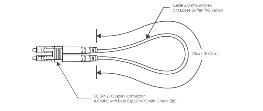
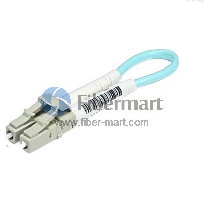
Fiber optic loopback incorprates two fiber optic connectors which are plugged into the output and input port of the equipment respectively. Therefore, fiber loopback cables can be classified by the connector types, such as LC, SC, FC, MTRJ. These fiber optic loopback plug connectors are compliant to IEC, TIA/EIA, NTT and JIS specifications. Besides, fiber optic loopback cables also can be divided into single mode and multimode fiber loopback. To describe this item clearly, I will take LC fiber optic loopback cable as an example, which is one of the most popular cables (as shown in the following figure). The LC fiber optic loopback cables support the test of transceivers featuring LC interface. They can comply with the RJ-45 style interface with low insertion loss, low back reflection and high precision alignment. LC loopback cables can be 9/125 single mode, 50/125 multimode or 62.5/125 multimode fiber type.
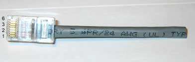
ytr

RJ45 Loopback Cable

A Gigabit RJ45 loopback cable is an exceedingly user friendly cable tester. It looks like a simple plug at first glance, but the compact and rugged design makes it highly portable and usable in the tightest corners. All you have to do is to simply plug the Gigabit RJ45 loopback into the jack that you want to test or the one you are suspicious about. If the link LED on your switch is active, it means that the connection is operating perfectly. The RJ45 loopback cable will negate the necessity to carry a bulky network hub around.

sc

How to build the loopback cable simplified?

If you are handy with building ethernet cables, the simple explanation is;

  1. Redirect Pin 1 to Pin 3 and Pin 2 to Pin 6.
  2. Make sure you create tight twists to account for signal interference at such a short length.

4

How to build a loopback cable illustrated?

Step 1. Get a pair of approximately 4 inches in length of cat 5 cable.

Step 2. Leave approximately 1/2 inch at end and start twisting, very tightly.

Note: If your fingers start to hurt, you may want to use a tool to help with the twisting. Notice how tightly wound the cable is. If the twists are not close enough the loopback will not work. Please twist to match picture.

Step 3. After twisting is done, fold cable and line up the ends. Cut if you must to line up cables. Line up the cables so that the cables are in the proper alignment to prepare for insertion into RJ-45 end.

 Step 4: Insert cable into RJ-45 end. (do not crimp yet.) Remember, 1236 pins.

Step 5. Insert plastic tubing over the wire and into the RJ-45 end. Now crimp the end with a crimping tool.

Note: When you first plug in the loopback cable, wait approximately 10 seconds to get a link light. No more carrying around a hub just to get a link light.

5

Conclusion

All in all, If we know what a is loopback cables and know how to create loopback cables, it will bring many benefits to our work and life.loopback cables play an important role in troubleshooting in laboratories and manufacturing environments. They facilitate the testing of simple networking issues and are available at very low costs. There are many loopback cable manufactures on the market, providing single mode and multimode fiber optic loopback plugs available with FC, LC, MT-RJ, SC connectors. Fiber-Mart is one of the fiber loopback cable providers, all loopback cables are precision terminated and feature extremely low loss characteristics for transparent operation in the test environment.

Five things you should know before your next installation

by http://www.fiber-mart.com

There are five things you should know before your next installation in order to avoid potential network failure and reduce your risk of costly mistakes.
1 Know your contractor
2 Increase error-free work with trained technicians
3 Ensure a quality installation with quality fiber optic products
4 Require a 25-year warranty for additional network protection and coverage
5 Request system testing results to ensure cabling system is properly functioning
Know your contractor
fiber optic installation is only as good as the products and the contractor you select. By choosing a reputable manufacturer such as Corning Cable Systems, half the battle is eliminated. However, choosing an installer for your thnext project can be time consuming and even frustrating at times. Utilizing the Network of Preferred Installers gives you reassurance that your installer is a handpicked, first-rate choice. Our by-invitation-only network means less financial risk of expensive mistakes and a higher probability of your complete satisfaction.
Increase error-free work with trained technicians
The bulk of improper installations are due to untrained or uncertified technicians. By making certain your contractor’s company has received proper hands-on training, you reduce the possibility of onsite cabling errors. All Preferred Installers within our network have received training on Local Area Network (LAN) design and hands-on product training. Because all training requirements must be renewed every two years, this means your installer is up-to-date on current installation methods, testing procedures, and product knowledge.
Ensure a quality installation with quality fiber optic products
The amount of information carried in two strands of optical fiber would require a copper cable four inches in diameter. When considering the space constraints, required bandwidth, and long distance transmission needs in today’s applications, fiber optic products are the only viable choice. Easy installation and upgrades allow you to meet future growth needs and install spare fiber today for a more economical choice than installing additional cables later. Corning Cable Systems LANscape® Solutions gives you quality products for all your fiber optic needs to reduce your risk of network failure.
Require a 25-year warranty for additional network protection and coverage
An extended warranty helps protect you from unexpected repair bills and provides the peace of mind that comes along with the Corning Cable Systems 25-year guarantee on its LANscape Solutions. Our warranty is simple. If a component fails, we replace it – no questions asked. By taking advantage of this additional coverage, your network is ensured to continue operating at its highest performance.
Request system testing results to ensure cabling system is properly functioning
Fiber optic testing of newly installed systems not only verifies that the system meets its design requirements, but also creates a performance baseline for all future testing and troubleshooting of that system to support the evaluation of warranty claims, should they ever arise. Corning Cable Systems requires that all fiber optic systems installed by members of the Network of Preferred Installers be tested to a minimum set of standards. This testing will ensure that the data necessary to properly evaluate any future system malfunctions will be available. The result will be better and faster service to you. Furthermore, by requiring a copy of your system’s bill-of-materials and design documents, we are able to quickly process potential claims to get your network back up and running once more.

MPO/MTP Trunk Cable Advantages

by http://www.fiber-mart.com

A specific lengths pre-assembled MTP/MPO Trunk cable with 12 or 24 fibers is delivered to data center for easy installation, because an It is impossible to manually to assemble MPO/MTP plug connector with 12 or 24 fibers on site during installation.
The advantages of MPO/MTP Trunk cable with the following advantages
• Higher Quality
Higher quality is usually achieved through factory assembly and inspection of individual parts. A factory-prepared inspection certificate is also useful for longterm documentation and in turn quality assurance purposes.
• Minimum Skew
A crucial factor in achieving a successful parallel optical connection is keeping the signal offset (skew) between the four or ten parallel fibers to an absolute minimum. Only in this way can information be successfully re-synchronized and re-combined at its destination. Factory-assembled trunk cables allow skew to be measured, minimized and logged.
• Shorter Installation Times
Pre-assembled MPO cable systems provide plug-and-play advantages and can be inserted and set up immediately.
This reduces installation time enormously
• Better Protection
Because they are completely assembled at the factory, cables and plug connectors remain completely protected from
environmental influences. Optical fibers that lie open in splice trays are at a minimum exposed to ambient air and may age faster as a result.
• Smaller Cable Volumes
Smaller diameters can be realized in MPO cabling systems that are produced from loose tube cables. The results are
correspondingly smaller cable volumes, better conditions for acclimatization in the data center and a lower fire load.
• Lower Overall Costs
When splice solutions are used, a few factors that are not always foreseeable boost total costs: time-intensive,
equipment-intensive splicing, needs for specialty works, bulk cables, pigtails, splice trays, splicing protection, holders. In contrast, pre-assembled trunk cables not only bring technical advantages, but usually result in lower total costs than splicing solutions.

Solid vs Stranded Cable – Which one should i Choose?

by http://www.fiber-mart.com

If you are on the fence as to whether you should use solid vs stranded cable, you are not alone. People all around the world struggle with this decision and there are no clear cut answers. The best option for you hinges on the nuances of your particular situation. Let’s take a look at the differences between the two types of cables and examine instances where one will function better than the other.
Solid vs Stranded Cable: The Basics
Solid cable is built with one strand or the core of a wire that has non-conductive material for insulation. This type of cable is used for home electrical wiring, wiring for breadboards and other situations where wires are not required to be constantly flexed. Stranded cable is made up of a collection of small gauge wires that are insulated and compressed with materials that are non-conductive. This type of cabling is typically used in situations where wire must be routed into cramped spaces. It is also used in areas where there is considerable flexing or vibrations. Examples include speaker wire, headphone cables and appliance cables.
Situations Where Stranded Cables are Ideal
Those who require cabling for intricate purposes such as circuit boards or electronic devices will favor stranded wires as they’ll remain intact and protected even if twisted or bent when connecting electrical components.
Situations Where Solid Cables are Ideal
Those who work outdoors or use heavy duty applications might expose the cables to corrosive particles, erratic movements and harsh weather conditions. Solid cables are best for these types of situations.
The Benefits of Solid Cables
Solid cables are often favored because they usually more affordable than the stranded variety due to their cheaper production costs. These cables are simple yet quite durable. As single, thick strands of cable, they are quite resistant to threats and very easy to produce. Solid cables also have a much more compact diameter compared to stranded cables. Yet this reduced size does not reduce the current carrying ability of solid cables. Add in the fact that solid cables are not as prone to failure as a result of corrosion and it is easy to see why they are held in high regard.
The Disadvantages of Solid Cables
Though solid cables have plenty of laudable characteristics, they also have a few flaws. One of the main problems with solid cables is that they are usually only sold in small gauges. Also, if there is constant flexing or vibrations, the cable could eventually wear down and break, creating the need for a replacement. Therefore, solid cables are not optimal for applications like robotics or vehicles that require a considerable amount of movement. If the cable must be bent into awkward shapes, the solid cable won’t have the appropriate amount of malleability and fortitude to remain fully intact.
Benefits of Stranded Cables
Stranded cables are easier to route in comparison to solid cables. They are also extremely flexible. Stranded cables can withstand an incredible amount of vibrations and flexing without fatiguing and eventually breaking. As a result, you won’t have to replace your stranded cables as often as will be necessary with solid cables.
Disadvantages of Stranded Cables
Stranded cables are far from perfect. Their diameter is quite large yet they provide a similar carrying capacity as solid cables. They are also more expensive as their production costs are considerably higher than solid cables. These costs are higher due to the complex manufacturing process that is required to develop these intricate wires. Also, stranded cables are much more likely to falter as a result of corrosion from capillary action. It is also worth noting that stranded cables are not ideal for preventing electronic interference as the air channels in between each strand amplify the “skin effect” created by the magnetic fields along the cable’s surface.
Be sure to take each of the factors listed above into account before making a commitment to either solid vs stranded cable for your home or business project.

About Hidden Cable Cabling, You Must Know the Hidden Rules

This article said something about Hidden Cable Cabling, You Must Know the Hidden Rules.

1. People participating in the construction should follow the following:
1.Wear suitable clothes
2.Guarantee the safety of the work area
3. Use safe, qualified tools
4.Formulate construction safety measures in advance

www.fiber-mart.com1

2. Cable laying requirements:
1.Before the fiber patch cable is laid, check whether the specifications, routes, and locations conform to the design rules.
2. The laying of the cable should be straight, do not produce a circle and so on, do not have damage.
3.Before laying out the cable, there must be marks on both ends of the cable, indicating the start and end positions. The label should be used as far as possible.
4.Signal cables, power cables, twisted-pair cables, and other weak cables should be placed as far apart as possible.
The cabling should be redundant. In the secondary exchange room and between the equipment twisted pairs, 3-6 meters must be reserved and the working area should be 0.3-0.6 meters.
5.When laying cables, the distance between the fulcrums of the cables hanging during the traction should not exceed 1.5 meters.

www.fiber-mart.com2

 3. Take the line:

Pull the cable from the cable box

a: Remove the plastic plug

b: Pull a few meters of cable through the outlet hole.

c: Pull out the required length of cable, cut it, slide the cable back into the slot, leaving 5 cm outside.

www.fiber-mart.com3

4. cable processing:

a.Use a diagonal pliers to open the “1” pattern outside the plastic.
b.Hold the fiber patch cable firmly in one hand. Use a long nose pliers to hold one end of the nylon pull string and pull it away from the end of the cable. The length is determined as required.
c.Cut off the useless leather jacket.

www.fiber-mart.com4

5. cable traction:

When pulling multiple pairs of twisted pairs, bundle multiple cables into one bundle and let them terminate.
2.Use an electrician to glue tightly around the cable and wind 5-6 meters outside the end.
3.Pull the rope through the electrical cable with a good cable and knot it.
Note: If you loosen the connection point while pulling the cable, you must retract the cable, and then make a firm connection.

www.fiber-mart.com5

Horizontal wiring considerations:
1) Pipeline routing
Pipeline routing is when the concrete has been buried in the pipeline, the pipeline  traction  cable wire or wire, construction time to understand the pipeline map, make a construction plan.
If there is no embedded pipe, it should be done synchronously with the decoration, so that it is easy to wire and look beautiful and prevent rework.

www.fiber-mart.com6

2)In ceiling wiring:

a.Obtain a construction plan and determine the route.
B. Along the design route, open the ceiling and slowly push the panels apart with both hands.
Put multiple cable boxes side by side with the line up.
d. From the end furthest from the wiring closet, draw the end of the cable along the cable tray over the ceiling of the ceiling corridor.
e.Move the ladder to the next hole in the suspended ceiling until the rope reaches the end of the corridor.

Fiber-Mart offers a wide variety of fiber optic cables, jumpers, Any questions or needs welcome to communicate with us: product@fiber-mart.com.

OM4 fiber optic cabling

by http://www.fiber-mart.com

OM4 Specifications
How does OM4 compare to OM1, OM2, OM3, and single mode? There are significant differences between most of the standardized types of glass. A select few of the major attributes of these different glass types are shown below to highlight the differences.
It is important to note that OM4 glass is not necessarily designed to be a replacement for OM3. Despite the relatively long-standing availability of OM4, there are no plans to obsolete OM3 fiber optic cabling. For most systems, OM3 glass is sufficient to cover the bandwidth needs at the distances of the current installation base. Most system requirements can still be reliably and cost effectively achieved with OM3, and this glass type will remain available for the foreseeable future.
Despite the availability of OM4 glass, OM3 is quite capable of 40 and 100 Gb/s applications albeit at significantly shorter distances than OM4. The primary benefit that OM4 provides is additional reach at extended bandwidth at an overall cost still less than that of an OS2 singlemode system. In other words, OM4 provides a solution that allows more installations to avoid the significantly higher costs of singlemode systems.
OM4 Compatibility
Additionally, OM4 provides an opportunity to future-proof cabling infrastructure. OM4 is completely backwards-compatible with existing OM3 systems. As a result, these two grades of glass are interchangeable within the transmission distance limitations outlined above. The additional bandwidth and lower attenuation of OM4 provide additional insertion loss margin. As a result, users of OM4 gain additional safety margin to help compensate for less-than-ideal cabling installations as well as provide margin for degradation due to moves, adds, and changes over the life of the installation.
As increased bandwidth requirements are called out in new installations, particularly 40 and 100 Gb/s standards, transmission distances over fiber optic cables contained in existing infrastruOM4-LC-LC-Patch-Cord-1cture may become increasingly limited. Increasingly, these higher bandwidth system requirements have dictated a need to transition from cost-effective multi-mode systems to more costly single-mode systems. Until OM4 was formally specified, many next-generation 40 and 100 Gb/s applications would have had to make the leap to single-mode system solutions. OM4 effectively provides an additional layer of performance that supports these applications at longer distances, thereby limiting the number of installations that truly require OS2 singlemode fiber. OM4 can provide a minimum reach of 125m over multimode fiber within the 40 and 100 GbE standards.