Multimode Fiber Optic Patch Cable Overview

by http://www.fiber-mart.com

We know that fiber optic patch cables play a very important role in the connection between devices and equipment. When talking about fiber optic patch cables, we usually divide them into multimode fiber optic patch cables and singlemode fiber optic patch cables according to the modes of the cable. What is multimode fiber optic patch cable? How many types of multimode patch cables are there? And what is the difference between multimode and singlemode patch cables? What are the applications of multimode patch cables? This text will solve those questions one by one.
Introduction
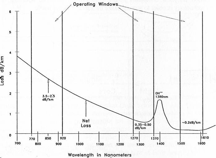
Multi-mode fiber patch cables are described by the diameters of their core and cladding. There are two different core sizes of multi-mode fiber patch cords: 50 microns and 62.5 microns. Both 62.5 microns and 50 microns patch cable feature the same glass cladding diameter of 125 microns. Thus, a 62.5/125µm multi-mode fiber patch cable has a 62.5µm core and a 125µm diameter cladding; and a 50/125µm multi-mode fiber patch cable has a 50µm core and a 125µm diameter cladding. The larger core of multi-mode fiber patch cords gathers more light and allows more signals to be transmitted, as shown below. Transmission of many modes of light down a multi-mode fiber patch cable simultaneously causes signals to weaken over time and therefore travel short distance.
Types of Multimode Fiber Optic Patch Cable
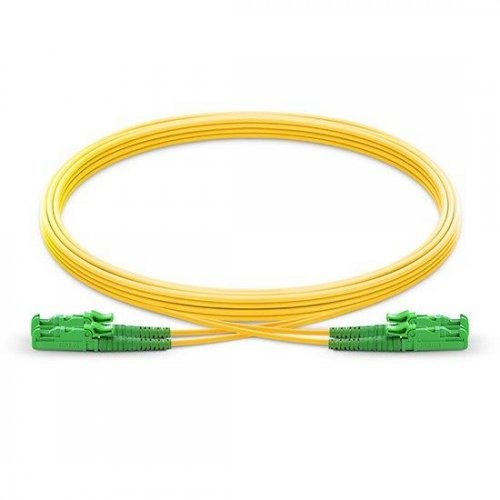
Multimode fiber optic cables can be divided into OM1, OM2, OM3, and OM4 based on the types of multimode fiber. The letters “OM” stands for optical multimode. OM1 and OM2 belong to traditional multimode fiber patch cable, while OM3 and OM4 belong to the new generation fiber patch cable which provides sufficient bandwidth to support 10 Gigabit Ethernet up to 300 meters. The connector types include LC, FC, SC, ST, MU, E2000, MPO and so on. Different type of connector is available to different equipment and fiber optic cable.
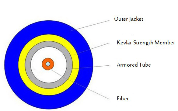
By the materials of optic fiber cable jackets, multimode fiber patch cord can be divided into four different types, PVC, LSZH, plenum, and armored multimode patch cable. PVC is non-flame retardant, while the LSZH is flame retardant and low smoke zero halogen. Plenum is compartment or chamber to which one or more air ducts are connected and forms part of the air distribution system. Because plenum cables are routed through air circulation spaces, which contain very few fire barriers, they need to be coated in flame-retardant, low smoke materials. Armored fiber patch cable use rugged shell with aluminum armor and kevlar inside the jacket, and it is 10 times stronger than regular fiber patch cable.
Difference Between Singlemode and Multimode Patch Cables
Multimode and singlemode fiber optic patch cables are different mainly because they have different sizes of cores, which carry light to transmit data. Singlemode fiber optic patch cables have a core of 8 to 10 microns. Multimode fiber patch cable allows multiple beams of light passing through, while singlemode fiber cable allows a single beam of light passing through. As modal dispersion happens in multimode fiber cable, the transmission distance is relevantly nearer than singlemode fiber cables. Therefore, multimode fiber optic patch cable is generally used in relevantly recent regions network connections, while the singlemode fiber cable is often used in broader regions.
Applications of Multimode Fiber Optic Patch Cable
Multi-mode fiber patch cables are used to connect high speed and legacy networks like Gigabit Ethernet, Fast Ethernet and Ethernet. OM1 and OM2 cables are commonly used in premises applications supporting Ethernet rates of 10Mbps to 1Gbps, which are not suitable though for today’s higher-speed networks. OM3 and OM4 are best multimode options of today. For prevailing 10Gbps transmission speeds, OM3 is generally suitable for distance up to 300 meters, and OM4 is suitable for distance up to 550 meters.
Conclusion
Fiber optic patch cords are designed to interconnect or cross connect fiber networks within structured cabling systems. Typical fiber connector interfaces are SC, ST, and LC in either multimode or singlemode applications. Whether to choose a singlemode or multimode fiber patch cable, it all depends on applications that you need, transmission distance to be covered as well as the overall budget allowed.Multimode Fiber Optic Patch Cable Overview

Introduction of Loopback Cable  

When testing the transmission equipment, fiber optic loopback device is often used as the testing tool. It is known as the routing of electronic signals, digital data streams, or flows of items back to their source without intentional processing or modification. Fiber optic loopback is widely used for various applications. In terms of telecommunication, loopback is a hardware or software method to feed a received signal or data back to the sender. It is very useful for solving physical connection problems.This post will be a guide on how to choose a right loopback cable for specific transceiver module.

What is Loopback Cable?

When testing the transmission equipment, fiber optic loopback device is often used as the testing tool. It is known as the routing of electronic signals, digital data streams, or flows of items back to their source without intentional processing or modification. Fiber optic loopback is widely used for various applications. In terms of telecommunication, loopback is a hardware or software method to feed a received signal or data back to the sender. It is very useful for solving physical connection problems.This post will be a guide on how to choose a right loopback cable for specific transceiver module.

111

Types of Fiber Optic Loopback

So, what is exactly the fiber optic loopback? Before deciding which loopback cable to use, we should firstly know the structure and classification of fiber loopback cable.By diagnosing the problems of optical equipment, fiber optic loopback provides an easy way to test the performance of the optical network devices. Generally, fiber optic loopback cable and fiber optic loopback module are both fiber optic loopbacks. Fiber optic loopback cable is the traditional fiber optic loopback with a visible cable. It is equipped with two fiber optic connectors on each end of the cable. When sticking the connectors together, the cable will shape like a loop. As for fiber optic loopback module, the biggest difference is that it has a enclosure to protect the inside cable. And the looped space is reduced for an easier usage and economic package.According to the optical connector type of the loopback, fiber loopback cables can be divided to LC, SC, FC, ST, MTP/MPO, E2000, etc. In testing fiber optic transceiver modules, the most commonly used are LC, SC and MTP/MPO loopback cables.

99

Figure 1: LC & SC Loopback Cable

The LC and SC loopbacks are made with simplex fiber cable and common connectors; it’s not difficult to understand their configurations. As for the MTP/MPO loopback, it is mainly used for testing parallel optics, such as 40G and 100G transceivers. Its configuration varies since the fiber count is not always the same in different applications.

8 Fibers MTP/MPO Loopback Cable Configuration

In a 8 fibers MTP/MPO loopback, eight fibers are aligned on two sides of the connector, leaving the central four channels empty. And the fibers adopt a straight configuration of 1-12, 2-11, 5-8, 6-7. The polarity channel alignment is illustrated in the following figure.

88

Figure 2: 8 Fibers Loopback Polarity Channel Alignment

12 Fibers MTP/MPO Loopback Cable Configuration

The only difference between the 12-fiber MTP loopback and the 8-fiber loopback is that the central four channels are not empty. Its alignment is 1-12, 2-11, 3-10, 4-9, 5-8, 6-7.

77

Figure 3: 12 Fibers Loopback Polarity Channel Alignment

24 Fibers MTP/MPO Loopback Cable Configuration

The 24 fibers MTP loopback also adopts type 1 polarity. Its alignment design is shown below.

66

Figure 4: 24 Fibers Loopback Polarity Channel Alignment

How to Use Loopback Cable?

The loopback cables are often used in conjunction with testing software to “loop” traffic right back into the port. If the data sent out into the loopback plug is identical to the data received from the loopback plug, you can assume that the basic communication functions of the port are working properly. So the common application of loopback cable is Loopback Test.

554

Loopback Test

Fiber loopback cable is often utilized to check whether the transceiver module is working perfectly as designed. As we all know, transceiver module has two ports, a transmitter port and a receiver port. The former one is to send out laser signals and the latter is to receive signals. When performing the loopback test, the fiber loopback cable can be directly plugged into the output and input port of transceiver module respectively (the ports at the ends of the connection must be compatible). Thus, during the testing process, the loopback cable directly routes the laser signal from the transmitter port back to the receiver port. Then we can compare the transmitted pattern with the received pattern to troubleshoot a defective node in the network. Fiber optic loopback testing is the easiest way to ensure that the transceiver works faultlessly. When selecting a suitable fiber loopback for the transceiver, we should consider the connector type, polish type, and cable type.

Application

When it comes to practical application, fiber optic loopback test is often employed for checking fiber optic transceivers. Since transceiver has two ports for receiving and transmitting the light signal, it is necessary to test the ports to see whether they are still under operation. Thus, fiber optic loopback test is the most convenient way for transceiver maintenance. The testing process is by routing the laser signal from the transmitter port back to the receiver port. Then the transmitted pattern is compared with the received pattern to make sure they are identical and have no error.

Conclusion

All in all, loopback cables play an important role in troubleshooting in laboratories and manufacturing environments. They facilitate the testing of simple networking issues and are available at very low costs.Similar to other cables, it also has multiple classifications of fiber types, connector types for different needs. The deployment of fiber optic loopback components has greatly saved the trouble for device checking. There is no doubt that using fiber optic loopback is an effective method in fiber optic communication. There are many loopback cable manufactures on the market, providing single mode and multimode fiber optic loopback plugs available with FC, LC, MT-RJ, SC connectors. Fiber-Mart is one of the fiber loopback cable providers, all loopback cables are precision terminated and feature extremely low loss characteristics for transparent operation in the test environment.I believe you can find a suitable products for your devices in Fiber-Mart. please contact us: product@fiber-mart.com.

Understanding Loss in Fiber Optic & How to Reduce It ?

Fiber optic cable, which is lighter, smaller and more flexible than copper, can transmit signals with faster speed over longer distance. However, many factors can influence the performance of fiber optic transmission. Losses in optical fiber are negligible issues among them, and it has been a top priority for every engineer to work with and figure out solutions for.

Fiber optic cable, which is lighter, smaller and more flexible than copper, can transmit signals with faster speed over longer distance. However, many factors can influence the performance of fiber optic transmission. Losses in optical fiber are negligible issues among them, and it has been a top priority for every engineer to work with and figure out solutions for.

Light traveling in an optical fiber loses power over distance. The loss of power depends on the wavelength of the light and on the propagating material. For silica glass, the shorter wavelengths are attenuated the most (see Fig. 1). The lowest loss occurs at the 1550-nm wavelength, which is commonly used for long-distance transmissions.

44

Transmission of light by fibre optics is not 100% efficient. There are several reasons for this including absorption by the core and cladding (caused by the presence of impurities) and the leaking of light from of the cladding. When light reflects off the cladding /core interface it actually travels for a short distance within the cladding before being reflected back. This leads to attenuation (signal reduction) by up to 2db/Km for a multi-mode fibre. For example, with this level of attenuation, if light travelled over 10kM of cable only 10% of the signal would arrive at the following end.

The amount of attenuation for a given cable is also wavelength dependent. Figure 1 shows the attenuation profile for the two main types of fibre; multi-mode and single-mode cable (described in detail below). The absorption peak at 1000nm is caused by the peculiarities of single mode fibre while the peak at 1400nm is caused by traces of water remaining in the fibre as an impurity. Due to this water absorption peak there are two standard single-mode wavelengths in use, 1310nm and 1550nm. 1310nm has been a standard for many years, only now is there a trend towards using 1550nm brought about by the need to extend the distances between repeaters.

The loss of power in light in an optical fiber is measured in decibels (dB). Fiber optic cable specifications express cable loss as attenuation per 1-km length as dB/km. This value is multiplied by the total length of the optical fiber in kilometers to determine the fiber’s total loss in dB.

Optical fiber light loss is caused by a number of factors that can be categorized into extrinsic and intrinsic losses:

  • Extrinsic
  • Bending loss
  • Splice and connector loss
  • Intrinsic
  • Loss inherent to fiber
  • Loss resulting from fiber fabrication

1

Figure 1. Optical fiber operating wavelengths.

  • Fresnel reflection

Bend Loss. Bend loss occurs at fiber cable bends that are tighter than the cable’s minimum bend radius. Bending loss can also occur on a smaller scale from such factors as:

  • Sharp curves of thefiber core
  • Displacements of a few millimeters or less, caused by buffer or jacket imperfections
  • Poor installation practice

This light power loss, called microbending, can add up to a significant amount over a long distance.

Splice and Connector Loss. Splice loss occurs at all splice locations. Mechanical splices usually have the highest loss, commonly ranging from 0.2 to over 1.0 dB, depending on the type of splice. Fusion splices have lower losses, usually less than 0.1 dB. A loss of 0.05 dB or less is usually achieved with good equipment and an experienced splicing crew. High loss can be attributed to a number of factors, including:

  • Poor cleave
  • Misalignment of fiber cores
  • An air gap
  • Contamination
  • Index-of-refraction mismatch
  • Core diameter mismatch to name just a few.

Losses at fiber optic connectors commonly range from 0.25 to over 1.5 dB and depend greatly on the type of connector used. Other factors that contribute to the connection loss include:

  • Dirt or contaminants on the connector (very common)
  • Improper connector installation
  • A damaged connector face
  • Poor scribe (cleave)
  • Mismatched fiber cores
  • Misaligned fiber cores
  • Index-of-refraction mismatch

Loss Inherent to Fiber. Light loss in a fiber that cannot be eliminated during the fabrication process is due to impurities in the glass and the absorption of light at the molecular level. Loss of light due to variations in optical density, composition, and molecular structure is called Rayleigh scattering. Rays of light encountering these variations and impurities are scattered in many directions and lost.

The absorption of light at the molecular level in a fiber is mainly due to contaminants in glass such as water molecules (OH-). The ingress of OUT molecules into an optical fiber is one of the main factors contributing to the fiber’s increased attenuation in aging. Silica glass’s (Si02) molecular resonance absorption also contributes to some light loss.

Figure 1 shows the net attenuation of a silica glass fiber and the three fiber operating windows at 850, 1310, and 1550 nm. For long-distance transmissions, 1310- or 1550-nm windows are used. The 1550-nm window has slightly less attenuation than 1310 nm. The 850-nm communication is common in shorter-distance, lower-cost installations.

Loss Resulting from Fiber Fabrication. Irregularities during the manufacturing process can result in the loss of light rays. For example, a 0.1 percent change in the core diameter can result in a 10-dB loss per kilometer. Precision tolerance must be maintained throughout the manufacturing of the fiber to minimize losses.

Fresnel Reflection. Fresnel reflection occurs at any medium boundary where the refractive index changes, causing a portion of the incident light ray to be reflected back into the first medium. The fiber end is a good example of this occurrence. Light, traveling from air to the fiber core, is refracted into the core. However, some of the light, about 4 percent, is reflected back into the air. The amount being reflected can be estimated using the following formula:

2

At a fiber connector, the light reflected back can easily be seen with an optical time domain reflectometer (OTDR) trace. It appears as a large upward spike in the trace. This reflected light can cause problems if a laser is used and should be kept to a minimum.

The reflected light power can be reduced by using better connectors. Connectors with the “PC” (Physical Contact) or “APC” (Angle Physical Contact) designations are designed to minimize this reflection.

How to Reduce Losses in Optical Fiber?

In order to ensure the output power can be within the sensitivity of the receiver and leave enough margin for the performance degradation with the time, it is an essential issue to reduce the losses in optical fiber. Here are some common approaches in fiber link design and installation.

  • Make sure to adapt the high-quality cables with same properties as much as possible.
  • Choose qualified connectors as much as possible. Make sure that the insertion loss should be lower than 0.3dB and the additional loss should be lower than 0.2dB.
  • Try to use the entire disc to configure (single disc more than 500 meters) in order to minimize the number of joints.
  • During splicing, strictly follow the processing and environment requirements.
  • The connecting joints must have excellent patch and closed coupling so that can prevent the light leakage.
  • Make sure of the cleanliness of the connectors.
  • Choose the best route and methods to lay the fiber cables during design the construction.
  • 3
  • Select and form a qualified construction team to guarantee the quality of the construction.
  • Strengthen the protection work, especially lightning protection, electrical protection, anti-corrosion and anti mechanical damage.
  • Use high quality heat-shrinkable tube.

Summary

When it comes to high-quality fiber patch cables that help in reducing losses in optical fiber, Fiber-Mart offers bend insensitive fiber (BIF) patch cables with ultra low insertion loss (IL) and bend radius, ensuring high performance of data transmission.I believe you can find a suitable fiber optic patch cable for your devices in Fiber-Mart.please contact us: product@fiber-mart.com.


The difference between Simplex and Duplex Fiber Optic Cables

When talking about fiber optic patch cable, related products that firstly come to our mind are usually multimode and single mode fiber patch cable.Of course,there are still many other types. But as a beginners in this field might wonder what duplex and simplex fiber patch cables are. This text will introduce you about these cables. Before we come to simplex and duplex fiber patch cables, let’s firstly get familiar with the two words — simplex and duplex.

When talking about fiber optic patch cable, related products that firstly come to our mind are usually multimode and single mode fiber patch cable.Of course,there are still many other types. But as a beginners in this field might wonder what duplex and simplex fiber patch cables are. This text will introduce you about these cables. Before we come to simplex and duplex fiber patch cables, let’s firstly get familiar with the two words — simplex and duplex.

What Do Simplex and Duplex Mean?

According to the ITU-T definition, a simplex circuit is one where signals can flow in only one direction at a time. One end is the transmitter, while the other is the receiver and that is not reversible.

However, at other times, communications can flow in the reverse direction. That is half-duplex. Half-duplex system means a communication channel that operates in one direction at a time and may be reversible. A good analogy for half-duplex system will be two roads with a traffic controller at each end, in order to ensure smooth flow of traffic, the traffic controller only allows one direction at a time. But if one party transmits at the same time, a collision occurs, resulting in lost messages.

“Duplex” comes from “duo” that means “two”, and “plex” refers to “weave” or “fold”. A duplex system has two clearly defined paths with each path providing information in only one direction, that is A to B over one path, B to A over the other. Compared with half-duplex, a full-duplex system, or sometimes called double-duplex allows communication in both directions and allowing this to happen simultaneously. Just like the cellphone, both parties can speak and be heard at the same time.

Simplex Fiber Optic Cable:

Simplex Fiber Optic Cables will be used when a signal only needs to go in one direction. They are designed for production termination where consistency and uniformity are vital for fast and efficient operation.

Simplex Fiber Optic Cable consists of a single fiber,tight-buffered (coated with a 900 micron buffer over the primary buffer coating) with Kevlar (aramid fiber) strength members and jacketed for indoor use, and is used mostly for patch cord and backplane applications. Analog to digital data readouts, interstate highway sensor relays, and automated speed and boundary sensors (for sports applications) are all great uses of Simplex fiber optic cable. This form of fiber cable can be cheaper than Duplex cables, because less material is involved. Simplex Fiber Cable is a single fiber available in single mode, multimode, or polarization maintaining, and they can meet the strength and flexibility required for today’s fiber interconnect applications. We also supply Riser, Plenum rated constructions and LSZH jacket.

Duplex Fiber Optic Cable:

Duplex Fiber Optic Cables consist of two fibers joined by a thin connection between the two jackets. Either single mode or multimode,they are used in applications where data needs to be transferred bi-directionally. One fiber transmits data one direction; the other fiber transmits data in the opposite direction. Larger workstations, switches, servers, and major networking hardware tends to require duplex fiber optic cable.

Duplex fibers types:

Half-duplex: Data may only be transmitted in one direction at a time.

Full-duplex: Data is transferred in two directions simultaneously.

Other duplex infomation:A duplex communication system is a point-to-point system composed of two connected parties or devices that can communicate with one another in both directions, simultaneously. Now, Duplex systems are employed in many communications networks, either to allow for a communication “two-way street” between two connected parties or to provide a “reverse path” for the monitoring and remote adjustment of equipment in the field.

Some Tips To Choice Simplex And Duplex Fiber Cable

When purchasing a fiber optic cable, it is important to understand the different varieties of core characteristics that are available within the cable itself. Each of these different characteristics will have different effects on your ability to transmit information reliably, and these different characteristics also affect the cabling project. You must search the cost of fiber optic cable if you bought the cable. Now, let’s take a look at the most common fiber optic cables.

Simplex Fiber Cable

A simplex fiber cable consists of a single strand of glass of plastic fiber, and is used for applications that only require one-way data transfer. Simplex fiber is most often used where only a single transmit and receive line is required between devices or when a multiplex data signal is used (bi-directional communication over a single fiber). Simplex fiber is available in singlemode and multimode. For example, an interstate trucking scale that sends the weight of the truck to a monitoring station or an oil line monitor that sends data about oil flow to a central location.

Duplex Fiber Cable

A duplex fiber cable consists of two strand fibers of glass or plastic. Typically found in a “zipcord”(side-by-side) construction format, this cable is most often used for duplex communication between devices where a separate transmit and receive are required. Duplex fiber is available in singlemode and multimode. Use multimode duplex fiber optic cable or single mode duplex fiber for applications that require simultaneous, bi-directional data transfer. Workstations, fiber switches and servers, fiber modems, and similar hardware require duplex fiber cable.

Cable Design Criteria For The Pulling Strength,Water Protection,Fiber Code Ratings

Pulling Strength: Some cable is simply laid into cable trays or ditches. So pull strength is not too important. But other cable may be pulled through 2 km or more of conduit. Even with lots of cable lubricant, pulling tension can be high. Most cables get their strength from an agamid fiber, a unique polymer fiber that is very strong but does not stretch – so pulling on it will not stress the other components in the cable. The simplest simplex cable has a pull strength of 100-200 pounds, while outside plant cable may have a specification of over 800 pounds.

Water Protection: Outdoors, every cable must be protected from water or moisture. It starts with a moisture resistant jacket, usually PE (polyethylene), and a filling of water-blocking material. The usual way is to flood the cable with a water-blocking gel. It’s effective but messy – requiring a gel remover. A newer alternative is dry water blocking using a miracle powder – the stuff developed to absorb moisture in disposable diapers. Check with your cable supplier to see if they offer it.

Fire Code Ratings: Every cable installed indoors must meet fire codes. That means the jacket must be rated for fire resistance, with ratings for general use, riser (a vertical cable feeds flames more than horizontal) and plenum (for installation in air-handling areas. Most indoor cables use PVC (polyvinyl chloride) jacketing for fire retardance. In the United States, all premises cables must carry identification and flammability ratings per the NEC (National Electrical Code) paragraph 770.

Conclusion

After reading the above statements, do you have a brief understanding of simplex fiber patch cable and duplex fiber patch cable? When choosing one over the other, the key factor is that the equipment requires one-way or bi-directional data transfer. Fiber-Mart has large numbers of simplex and duplex fiber optic patch cables, such as single mode simplex fiber patch cable, LC to LC duplex single mode patch cable, 10 gigabit multimode duplex cables, LC ST duplex patch cord and so on. I believe you can find a suitable fiber optic patch cable for your devices in Fiber-Mart.please contact us: product@fiber-mart.com.

How much do you know about MTP/MPO ?

With widespread deployment of 40G and 100G networks, high-density MTP/MPO cable solutions are also become more and more popular. Unlike traditional 2‐fiber configurations LC or SC patch cords, with one send and one receive, 40G & 100G Ethernet implementations over multimode fibers use multiple parallel 10G connections that are aggregated.

With widespread deployment of 40G and 100G networks, high-density MTP/MPO cable solutions are also become more and more popular. Unlike traditional 2‐fiber configurations LC or SC patch cords, with one send and one receive, 40G & 100G Ethernet implementations over multimode fibers use multiple parallel 10G connections that are aggregated. 40G uses four 10G fibers to send and four 10G fibers to receive, while 100G uses ten 10G fibers in each direction. MTP/MPO cable can hold 12 or 24 fibers in a connector, which greatly facilitates the upgrade to 40G and 100G networks. However, since there are so many fibers, the polarity management of the MTP/MPO cable may be a problem.

What is MTP/MPO Cable Assembly?

The core of MTP/MPO fiber assembly lies in its connector—MTP/MPO connector. MTP/MPO connector factory terminated assembly can house 6 to 72 fibers, with 12-fiber and 24-fiber arrays being the most common. MTP/MPO connector is available in a male version (with pins) or a female version (without pins). The pins ensure that the fronts of the connectors are exactly aligned on contact and that the endfaces of the fibers are not offset. There are guide grooves (keys) on the top side of the factory terminated MTP/MPO connector, which ensures that the adapter holds the connector with the correct ends aligned with each other. The push-pull design of MTP/MPO connector facilitates easier insertion and removal, making it a breeze when using with QSFP+ transceiver modules in 40/100G network.

1

What is MTP Modules and Harnesses ?

An obvious benefit to deploying a MTP-based optical network is its flexibility to transmit both serial and parallel signals. MTP to duplex connector transition devices such as modules and harnesses are plugged into the MTP trunk assemblies for serial communication. MTP Modules are typically used in lower-portcount break-out applications such as in server cabinets. MTP harnesses provide a significant increase in cabling density and find value in high port count break-out situations such as SAN Directors . The built-in modularity of the solution provides flexibility to easily configure and reconfigure the cabling infrastructure to meet current and future networking requirements. MTP harnesses and modules can be exchanged or completely removed from the backbone network to quickly adapt to data center MACs.

图片1444

MTP Modules in Data Centers

MTP modules typically are placed in a housing located in the cabinet rack unit space. Here the MTP trunk cable is plugged into the back of the module. Duplex patch cords are plugged into the front of the module and routed to system equipment ports. Integrating the MTP modules cabling solution into the data center cabinet can enhance the deployment and operation of the data center cabling infrastructure. As shown in the figure below, integrating the MTP modules into the cabinet vertical manager space maximizes the rack unit space available for data center electronics. MTP modules are moved to the cabinet sides where they snap into brackets placed between the cabinet frame and side panel. Properly engineered solutions will allow MTP modules to be aligned with low-port-count system equipment placed within the cabinet rack unit space to best facilitate patch cord routing.

MTP Harnesses in Data Centers

MTP harnesses are plugged into the backbone MTP trunk assemblies through an MTP adapter panel. The MTP adapter panel is placed in a housing that is also typically located in the cabinet rack unit space. MTP to LC 12-fiber break-out harnesses plug into the front of the adapter panels and are routed over to the director line cards where the LC duplex ends are plugged into the line card ports. These MTP harnesses are pre-engineered to a precise length with strict tolerances to minimize slack, while a small outside diameter allows for easy routing without preferential bend concerns. With a pre-engineered cabling management, not only is installation simplified, but the time required for SAN design and documentation is greatly reduced with port mapping architecture inherent to the design.

What is MTP/MPO Connectors?

Before explaining the polarity, it is important to learn about the structure of MTP/MPO connector first. Each MTP connector has a key on one side of the connector body. When the key sits on top, this is referred to as the key up position. In this orientation, each of the fiber holes in the connector is numbered in sequence from left to right. We will refer to these connector holes as positions, or P1, P2, etc. Each connector is additionally marked with a white dot on the connector body to designate the position 1 side of the connector when it is plugged in.

11
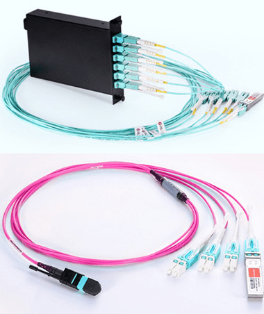
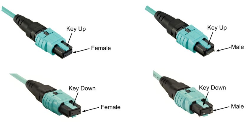
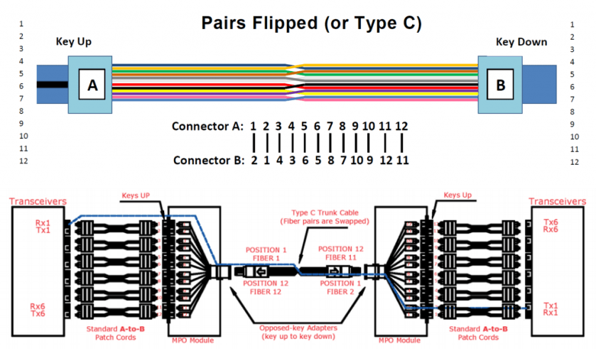
Since the MTP connectors can either key up and key down, there are two types of MPO adapters.
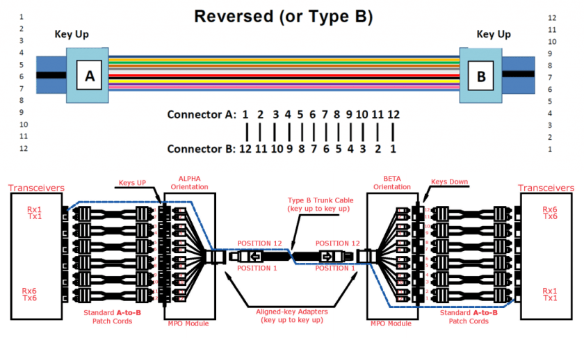
Type A: Key-up to key-down
Here the key is up on one side and down on the other. The two connectors are connected turned 180° in relation to each other.
Type B: Key-up to key-up
Both keys are up. The two connectors are connected while in the same position in relation to each other.

222

Two Polarity of Traditional Duplex Patch Cable

Classic duplex cables are available in a cross-over version (A-to-A) or a straight-through version (A-to-B) and are terminated with LC or SC connectors. Telecommunications Cabling Standard defines the A-B polarity scenario for discrete duplex patch cords, with the premise that transmit (Tx) should always go to receive (Rx) — or “A” should always connect to “B”. Therefore, A-B polarity duplex is very common in applications.

444

Three Polarity of MTP/MPO Multi-Fiber Cable

Unlike traditional duplex patch cables, there are three polarity for MTP/MPO cables: polarity A, polarity B and polarity C.

Polarity A

Polarity A MTP cables use a key up, key down design. Therefore, as shown in the figure below, the position 1 of one connector is corresponding to the position 1 of another connector. There is no polarity flip. Therefore, when we use polarity A MTP cable for connection, we must use A-B duplex patch cables on one end and A-A duplex patch cables on the other end. Since in this link, Rx1 must connect to Tx1. If we don’t use A-A duplex patch cable, according to the design principle of polarity A MTP cable, fiber 1 may transmit to fiber 1, that is to say Rx1 may transmit to Rx1, which may cause errors.

555

Polarity B

Polarity B MTP cables use a key up, key up design. Therefore, as shown in the figure below, the position 1 of one connector is corresponding to the position 12 of another connector. Therefore, when we use polarity B MTP cable for connection, we should use a A-B duplex patch cables on both ends. Since the key up to key up design help to flip the polarity, which makes fiber 1 transmit to fiber 12, that is the Rx1 transmits to Tx1.

666Polarity C

Like the polarity A MTP cables, polarity C MTP cables also use a key up, key down design. However, within in the cable, there is a fiber cross design, which makes the position 1 of one connector is corresponding to the position 2 of another connector. As shown in the figure below, when we use polarity C MTP cable for connection, we should use a A-B duplex patch cables on both ends. Since the cross fiber design help to flip the polarity, which makes fiber 1 transmit to fiber 2, that is the Rx1 transmits to Tx1.

777

Conclusion

Speed is paramount to a data center, therefore data center are always on the road to higher density data rates. Different polarity MTP cables may have different connection methods. No matter which type cable you choose, remember its design principle and choose the right cabling infrastructure for your network. MTP/MPO fiber optic cable assembly appears to be the best option to improve speed, agility and performance of the system. Considering the time saving, space efficiency and flexibility, it is worthwhile to make MTP/MPO cabling a part of your data center. Fiber-Mart has various MTP/MPO products, If you have any requirement of our products, please contact us: product@fiber-mart.com.

What fiber Patch Cables should we use in a harsh environment?

With the rapid development of optical communication, more and more fiber optic cables are increasingly used in different environments. Under harsh conditions, the ruggedness and durability of common fiber optic cables cannot meet operators’ requirements, especially for exceptional demanding applications. This post mainly introduces IP67 waterproof fiber optic cable & armored Fiber Patch Cablesuitable in harsh environment. All the types of waterproof fiber optic cables are available in Fiber-Mart.

With the rapid development of optical communication, more and more fiber optic cables are increasingly used in different environments. Under harsh conditions, the ruggedness and durability of common fiber optic cables cannot meet operators’ requirements, especially for exceptional demanding applications. This post mainly introduces IP67 waterproof fiber optic cable & armored Fiber Patch Cablesuitable in harsh environment. All the types of waterproof fiber optic cables are available in Fiber-Mart.

图片14

The two fiber patch cables are armored fiber patch cable and IP67 fiber patch cable. As most fiber cable failures are usually caused by fiber breaks and contaminants, the fiber cable and the termination points of the fiber links should all be well protected. And the two types of fiber cable can perfectly meet most requirements of harsh cabling environment.

  1. IP67 Fiber Patch Cable

IP67 waterproof fiber optic patch cable can be used in harsh environment, providing more convenience and extra protection for network systems. Even if there are various patch cables available on the market, which can be used in different applications, in most cases, they can only be installed in relatively protected environment where stay away from liquid, chemicals and animal biting. What if I want to use it in military network or extremely harsh environment? The following text will introduce a saviour in hostile surroundings—IP67 waterproof fiber optic patch cable.

Overview of IP67 Waterproof Fiber Optic Patch Cable

Waterproof fiber optic patch cable is mainly used in outdoor connection. It is designed with a stainless steel strengthened waterproof unit and armored outdoor PU jacketed cables. It can resist high temperature, and is suitable for use in harsh environments. Similar to standard fiber optic patch cables, waterproof fiber cables also have various types, including simplex, duplex, 12 fibers, 24 fibers, and various kinds of connect interfaces are optional, such as LC, SC, FC, ST, MPO, etc.

IP67 waterproof fiber cable meets ODVA (Open DeviceNet Vendors Association) standards and the IP66/67 environmental sealing ratings. IP67 waterproof fiber jumper connectors are designed according to the IEC60603-7 interface standard, which allows mating to other similar mechanical locking systems. In all, IP67 waterproof fiber optic patch cable is a low-cost and ideal alternative for industry, FTTA, or other harsh environmental conditions.

654

Why & Where to Use IP67 Waterproof Fiber Optic Patch Cable?

Compared to common fiber optic cables, IP67 waterproof fiber cables are endowed with the following features:

  • Corrosion-resistant, waterproof, dust-proof
  • High temperature stability, low insertion loss
  • Easy operation, reliable and cost-effective installation
  • Thread locking mechanism to ensure long-term reliable connection
  • Long-lasting and durable
  • Rugged design for extreme environments
  • High sealing performances for vacuum & under water applications

All of the above features make waterproof fiber cables suitable for outdoor application, such as:

  • Emergency repair quick connection system
  • Radio and television industry
  • Military exercise communication devices
  • Power industry emergency communication system
  • Oilfield, mining communication connection
  • Remote wireless base station
  • Railway signal control application
  • Intelligent substation communication
  • Video monitoring system

2.Armored Fiber Patch Cable

Unlike traditional fiber patch cables which are fragile and usually need careful operation, armored fiber patch cables are usually much more durable and flexible. Armored fiber patch cable usually has two jackets, one inner jacket and one outer jacket, between which there is a build-in steel tube. Some vendors also provide armored fiber cables with aluminum tube. This robust metal tube can provide optical fibers inside armored fiber cable from the impact and bite from animals. The most commonly used designs of armor used in armored fiber cables are interlock and corrugated. For most outside plant applications, the corrugated armored fiber cables are suggested. Now a lot of armored fiber patch cable uses interlock armor. During operation in data center, armored fiber patch cable can provide a more flexible cabling environment, because it has bend restrictor which can provide optical fibers from over bending. The following picture shows the structure of an armored fiber patch cable.

6544

With its durability and flexibility, armored fiber patch cables and armored fiber cable are widely deployed in today’s network. For data center applications, there is a wide selection of armored fiber patch cables, which are available from different connector type, fiber type, jacket type, fiber count, etc.

Conclusion

It is usually inevitable to deploy fiber cables in harsh environments for both indoor and outdoor applications. Rodents, like squirrels in outdoor and rats in data centers, are cable destroyers which like to bite or chew fiber optic cables. Except that, there are also many other challenges which can harm fiber optic cables and cause fiber failures, like dusts, water or other liquid, accidental impact, etc. Thus, enough protection should be provided for fiber optic network. Two types of fiber patch cables, which are specially designed for harsh cabling environments,can easyly find in Fiber-Mart. Welcome to contact with us: product@fiber-mart.com