Finding the right fiber optic connector for an application used to be a straightforward choice based on what was available, but now the number of fiber connectors on the market can be paralyzing. Design and performance improvements have resulted in a proliferation of styles and types of fiber optic connectors. Many fiber connectors currently on the market provide a wide range of terminal-to-terminal solutions, many of which can be terminated in the field.
EARLY FIBER OPTIC CONNECTORS
Old style fiber optic connectors like the Biconic are now obsolete, but they were cutting edge technology. AT&T derived the name Biconic from a conic-shaped ferrule centered around the fibers. Metal SMA connectors were the only choice for connecting multimode fibers until Japanese engineers developed ceramic ferrules.
Soon D4 and FC connectors used built-in keys as optical coupling repeaters with FC/PC and FC/UPC receptors. The ST bayonet-style connector followed quickly. SMA fiber connectors are declining in popularity, but ST fiber connectors are still industry standards. The Fiber Optic Association has a detailed history of connectors if you want a trip down memory lane.
CURRENT FIBER OPTIC CONNECTORS
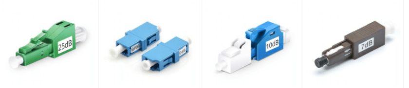
Most optical fiber connectors on the market today have LC duplex ports or MPO multi-fiber ports. The twin advantages of small size and high-density patching make them indispensable in most data centers using 40 GBPS or 100 GBPS broadband. Now you can choose between MXCs and PRIZMs with laser lenses instead of physical connectors.
CHOOSING THE RIGHT FIBER CONNECTOR
STEP ONE: NARROW YOUR CHOICE BASED ON THE APPLICATION
One way of finding the right fiber connector is to eliminate the ones you that won’t work, giving you a smaller set of choices to compare.
What type of hardware are you connecting?
Do you need connections at each end?
What about data transmission speeds, distance, and total connections?
Your insertion loss (IL), return loss (RL), and standards requirements will guide your decision about both the equipment and fiber connectors needed for your application. Next, decide whether or not to use pre-terminated cables based on your optical transceiver modules and bulkhead receptacles.
STEP TWO: NARROW YOUR CHOICE BASED ON THE OPERATING ENVIRONMENT
Your application’s operating environment is an essential factor in choosing a fiber optic connector. The environmental conditions, type of fiber, cable construction will limit the choices available. For example, field terminations are more demanding in extreme environments so a pre-polished connector is a better choice. The cable diameter will limit your options of jackets. Mechanical connectors are far more convenient that polishing in the field, but they have a limited range of operating temperatures. Adhesive fiber connectors need to be polished in the field for optimal performance, so they are a good choice if you are operating in a data center or any other reasonably accessible environment. Or you can challenge your skills with a Fusion Splice Connector for precision fitting.
STEP THREE: FINALIZE YOUR LIST BASED ON LIFE EXPECTANCY
You probably considered the life expectancy of your application when you set up your fiber network. A system built to last 30 years will be very different from the one you only need for a few months. Most cable systems fail at the connections, not the fiber itself. Fiber connectors show a decrease in performance after cleaning, repetitive mating and demating, and scratching. Polished fiber connectors often have a lifetime warranty, so check manufacturer’s websites. Pre-polished connectors have a shorter lifespan. Whichever type you choose, training your technicians to clean fiber connectors properly, unplug using the pulling grip instead of the connector, and dusting during mating extend the life.
CONCLUSION
There are many choices for fiber connectors on the market, but you can find the best match for your application by methodically narrowing down the options based on your application needs and operating environment. This will result in a limited list that you can reasonable research on manufacturer and review websites.