An optical attenuator is a passive device used to reduce the power level of an optical signal, either in free space or in an optical fiber. There are various types of them from the fixed ones, step-wise variable, and continuously variable.
Attenuators are usually used when the signal arriving at the receiver is too strong and hence may overpower the receiving elements. This may occur because of a mismatch between the transmitters/receivers, or because the media converters are designed for a much longer distance than for which they are being used.
Sometimes attenuators are also used for stress testing a network link by incrementally reducing the signal strength until the optical link fails, determining the signal’s existing safety margin.
Although fiber optic attenuators are normally used in SM (Single Mode) circuits, because this is where the stronger lasers are used for distance transmission, there are also multi mode attenuators available.
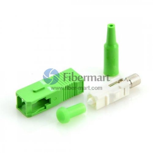
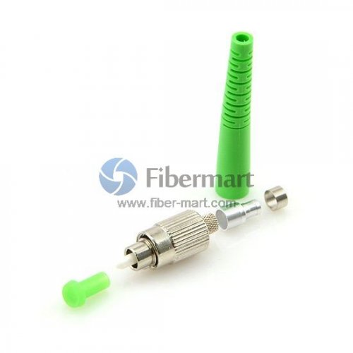
The most common version of attenuators are male to female units, often called plug-style or buildout style. These plug-style attenuators simply mount on one end of a fiber optic cable, allowing that cable to be plugged into the receiving equipment or panel.
There are also female to female (bulkhead) attenuators, often used to mount in patch panels or for connecting two fiber optic cables together. More expensive, but useful for testing, are variable attenuators which are adjustable between 1dB and 30dB.
Bear in mind that the dB ratings are a measure of signal strength and can sometimes be confusing. The chart below will give you an idea of the percent of attenuation of your signal for specific dB values.
Fiber optic attenuators are usually used in two scenarios.
The first case is in power level testing. Optical attenuators are used to temporarily add a calibrated amount of signal loss in order to test the power level margins in a fiber optic communication system. In the second case, optical attenuators are permanently installed in a fiber optic communication link to properly match transmitter and receiver optical signal levels.
How many types of Optical Attenuators (OA) can you find?
There are four different types of OA and they can take a number of different forms and are typically classified as fixed or variable attenuators. What’s more, they can be classified as LC, SC, ST, FC, MU, E2000 etc. according to the different types of connectors.
1. Fixed Attenuators: Fixed optical attenuators used in fiber optic systems may use a variety of principles for their functioning. Preferred attenuators use either doped fibers, or misaligned splices, or total power since both of these are reliable and inexpensive.
Inline style attenuators are incorporated into patch cables. The alternative build out style attenuator is a small male-female adapter that can be added onto other cables.
Non-preferred attenuators often use gap loss or reflective principles. Such devices can be sensitive to modal distribution, wavelength, contamination, vibration, temperature, damage due to power bursts, may cause back reflections, may cause signal dispersion etc.
2. Loopback Attenuators: Loopback fiber optic attenuator is designed for testing, engineering and the burn-in stage of boards or other equipment. Available in SC/UPC, SC/APC, LC/UPC, LC/APC, MTRJ, MPO for single mode application.
3. Built-in Variable Attenuators: Built-in variable optical attenuators may be either manually or electrically controlled. A manual device is useful for one-time set up of a system, and is a near-equivalent to a fixed attenuator, and may be referred to as an “adjustable attenuator”. In contrast, an electrically controlled attenuator can provide adaptive power optimization.
Attributes of merit for electrically controlled devices, include speed of response and avoiding degradation of the transmitted signal. Dynamic range is usually quite restricted, and power feedback may mean that long-term stability is a relatively minor issue.
The speed of response is a particularly major issue in dynamically reconfigurable systems, where a delay of one millionth of a second can result in the loss of large amounts of transmitted data.
Typical technologies employed for high-speed response include liquid crystal variable attenuator (LCVA), or lithium niobate devices.
There is a class of built-in attenuators that is technically indistinguishable from test attenuators, except they are packaged for rack mounting, and have no test display.
4. Variable Optical Test Attenuators: this type generally uses a variable neutral density filter. Despite the relatively high cost, this arrangement has the advantages of being stable, wavelength insensitive, mode insensitive, and offering a large dynamic range.
Other schemes such as LCD, variable air gap etc. have been tried over the years, but with limited success.
They may be either manually or motor control. Motor control gives regular users a distinct productivity advantage since commonly used test sequences can be run automatically.