A Passive Optical Network (PON) is a system that transmits all or most of the fiber cabling and signals to end-users. Depending on where the PON terminal is located, the system can be described as fiber-to-the-curb (FTTC), fiber-to-the-building (FTTB), or fiber-to-the-home (FTTH).
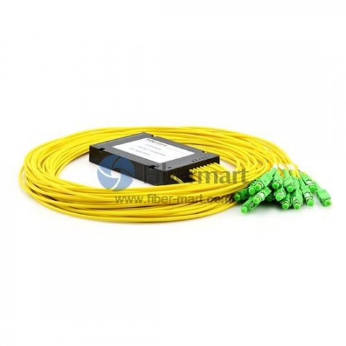
The optical distribution network does not contain any electronic devices and electronic power supply, ODN splitter consist of the passive components, and other components do not require expensive active electronic devices. A passive optical network includes an optical line terminal (OLT) installed at a central control station and a set of optical network units (ONUs) installed at customer side. The Optical Distribution Network (ODN) between the OLT and the ONU contains optical fibers as well as passive optical splitters or couplers.
The structure of the PON system is mainly composed of an Optical Line Terminal (OLT) at the ca0rrier’s office, an Optical Distribution Network (ODN) including passive optical components, an ONU (Optical Network Unit / ONT (Optical Network Terminal). The difference is that the ONT is directly located at the user end, and there are other networks between the ONU and the user, such as Ethernet) and the network element management system (EMS), and usually adopts point-to-multipoint Tree topology.
Introduction
Fiber is so cheap and easy to use, so FTTx (Fiber To The X, fiber access) as a new generation of broadband solutions are widely used to provide users with high-bandwidth, full-service access platform. The FTTH (Fiber To The Home, FTTH, the fiber is directly connected to the user’s home) is also known as the best business transparent network, is the ultimate way of access network development.
The FTTx is how to work? In many kinds of schemes, P2MP optical access mode PON (Passive Optical Network, passive optical network) is the best choice. PON is an optical distribution network (ODN) which is applied to an access network, an OLT and a plurality of client devices (ONU / ONT) through passive optical cables, optical splitters/combiners, etc., Connected network. As shown on the right.
• OLT (Optical Line Terminal, optical line terminal)
• ONU (Optical Network Unit, optical network unit)
• ONT (Optical Network Terminal, optical network terminal)
• ODN (Optical Distribution Network, optical distribution network)
Both the ONU and the ONT belong to the user equipment. The difference between them lies in that the ONT is located directly on the user end, and there are other networks between the ONU and the user, such as Ethernet.
The key point of “passive” is that the ODN between the OLT and the ONU is an optical access network without any active electronic equipment. Because of this “passive” feature, the purely PON network can avoid electromagnetic Interference and lightning effects reduce line and external device failure rates, improve system reliability, and reduce maintenance costs.
PON technology began to develop in the 1990s, ITU (International Telecommunication Union) started from APON (155 M), developed BPON (622 M), and to GPON (2.5 G); meanwhile, in this century, due to Ethernet technology widespread application, IEEE also developed EPON technology in Ethernet technology. At present, PON technologies for broadband access mainly include EPON and GPON, and the two adopt different standards. The future development is higher bandwidth, such as EPON / GPON technology has developed 10G EPON / 10G GPON, the bandwidth has been a higher upgrade.
Click here to learn more about the difference and comparison between GPON and EPON
PON Features
The complexity of PON lies in the signal processing technology. In the downlink direction, the switch sends the signal is broadcast to all users. In the uplink direction, each ONU must use some kinds of multiple access protocols such as TDMA (Time Division Multiple Access) protocols to complete the shared transmission channel information access. Currently used for broadband access PON technologies are: EPON and GPON.
PON Standards
• ITU-T G.983
APON (Passive Optical Network), This is the first passive optical network standard, which is based on ATM and is mainly used in commercial applications. BPON (Broadband Passive Optical Network), This is an APON-based standard that adds support for WDM, dynamic and high-speed uplink bandwidth allocation, and endurance. BPON also created a management interface standard OMCI, authorized between the OLT and ONU / ONT hybrid supplier network.
• IEEE 802.3ah
EPON or GEPON (Ethernet Passive Optical Network), This is an IEEE / EFM standard for data using Ethernet packets. The 802.3ah standard is now part of the IEEE 802.3 standard and there are now about 15 million EPON ports in use. In 2008, China vigorously developed EPON technology. It is estimated that as of the end of 2008, China had a total of 2 million EPON installation users.
• ITU-T G.984
GPON (Gigabit PON, Gigabit Passive Optical Network), This is a BPON standard development. GPON supports higher rates, enhanced security and optional Layer 2 protocols (ATM, GEM, Ethernet). In mid-2008, 900,000 lines had been installed by the company, and British Telecom And AT & T are conducting advanced trials.
• IEEE P802.3av
10G-EPON (10 Gigabit Ethernet PON) is an IEEE dedicated project that is backward compatible with 802.3ah standard EPON in order to achieve 10 Gbit/s. 10Gig EPON will use separate wavelengths for 10G and 1G downstream. 802.3av will continue to be isolated using separate wavelength TDMA for uplink between 10G and 1G. 10G-EPON will also be WDM-PON compatible (as defined by WDM-PON).This allows multiple wavelengths to be used in both directions It is possible.
• SCTE IPS910
RFoG (RFoverGlass) is an SCTE interface practice subcommittee standard for point-to-multipoint (P2MP) operation with wavelength planning compatible data PON solutions such as EPON, GEPON or 10Gig EPON.
PON technology status
The traditional downlink data flow of PON system adopts a broadcasting technology, and the uplink data flow uses TDMA technology to solve the problem of multiplexing signals in each direction of multi-user. The traditional PON technology uses WDM technology to implement single-fiber bidirectional transmission on optical fibers and solve the multiplexing transmission of signals in two directions. PON generally by the optical line terminal (OLT), optical splitter (ODU), the user terminal (ONU) 3 parts. Currently, PON technologies widely used in the current network include two mainstream technologies, EPON and GPON. The bandwidth for EPON uplink and downlink is 1.25 Gbit / s, the downlink bandwidth for GPON is 2.5 Gbit / s, and the uplink bandwidth is 1.25 Gbit / s.
Currently, in the actual FTTx application scenario, most EPON / GPONs only have an Ethernet interface, and POTS and 2M interfaces are optional. However, from the technical standards, EPON / GPON can achieve multi-service access such as IP service and TDM service and realize QoS classification.
EPON / GPON can transmit the clock synchronization signal. The frequency synchronization signal can be extracted from the external line through the STM-1 interface or the GE interface of the OLT. In this case, the OLT needs to support synchronous Ethernet, and can also be input from the external BITS on the OLT device The clock signal, as a common clock source of the PON, is kept in frequency synchronization with the clock source.
PON Standards Development
Although 10G EPON and PON have not yet been commercialized on a large scale, the PON technology at a rate of more than 10 Gbit / s is the focus and hot point of the research of ITU-T and FSAN in the past two years. The relevant technical standards of XG-PON1 have become mature, NG-PON2 standard after XG-PON1 ITU-T related standards for GPON, XG-PON1, and NGPON2 The framework has basically been completed. The emphasis on recent multi-wavelength extensions is the focus of recent technical studies where FSAN has identified TWDM-PON as the technology of choice for NG-PON2 in the future, but the G. multi-standard that standardizes multiple technologies in ITU-T SG15 has also been largely completed.
PON Advantages
• Energy consumption
Imagine the ongoing costs of energy-inefficient equipment and equipment needed to operate in traditional Ethernet LANs and the additional energy costs to cool or heat the closet space. Achieving More Than 50% Savings by Eliminating Active Switches, Uninterruptible Power Supplies (UPS) Devices, and Additional Power Demand is a year-by-year cost-effective annuity.
• Save space
The PON architecture requires a separate data center room, with splitters on each floor, usually hidden in a maintenance or electrical cabinet. Traditional Ethernet closets require more than 100 to 200 square feet of floor space per floor, and these spaces are returned to customers for functional or even potential revenue-generating space. Just reducing the weight of the ceiling wiring is amazing. BICSI announced that the traditional 114-port copper Ethernet design required 890 pounds of copper and fiber optic backbone; in contrast, the 114-port PON design required only 180 pounds of fiber optic cable, about one-fifth the size of a traditional design.
• Installation Savings
Which sounds easier? Installing and Terminating (5) Category 6A UTP cable to each hotel room, or (1) Fiber optic cable in each room … Each floor without cable tray, rack, and traditional cabinet. Few components require grounding and coding, and fire through holes are much smaller and less expensive.
• Safety
Passive optical networks LANs are naturally more secure than Ethernet LANs for the simple reason that optical fibers are not as conductive as copper. Unfortunately, electronic-based services are known as security risk points because copper emits electromagnetic radiation (EMR) signals. These signals contain all the information copper carries at the time and can be intercepted and reconstructed on nearby devices.
• Speed and bandwidth
We have already mentioned the potential of speed and bandwidth, which is why in the 90s we wanted to achieve the “fiber to the desktop” dream. The reality now is that, for example, new hotels that have moved to PON are now gaining the benefits of improved high-speed Internet access (HSIA) performance from their guests, improving customer satisfaction surveys and increasing occupancy rates.