Introduction to Fiber Optic Splice Closure

Fiber optic splicing is important for fiber connections. Fiber Optic Splice Closure is a fiber management product typically used with outdoor fiber optical cables. It provides space and protection for the fiber optic cable splicing and joint. Fiber splice closure is used for aerial, strand-mount FTTH “tap” locations where drop cables are spliced to distribution cables.

Fiber optic splicing is important for fiber connections. Fiber Optic Splice Closure is a fiber management product typically used with outdoor fiber optical cables. It provides space and protection for the fiber optic cable splicing and joint. Fiber splice closure is used for aerial, strand-mount FTTH “tap” locations where drop cables are spliced to distribution cables.

What is a fiber Optic Splice Closure?

In fact, except underground application, fiber optic splice closure is also used for aerial, strand-mount FTTH “tap” locations where drop cables are spliced to distribution cables. It is usally used with outdoor fiber optic cables which provides space for the outdoor fiber optic cables to be spliced together. The fiber optic splice closures and the fiber trays inside will protect the spliced fiber and the joint parts of the outdoor fiber cables.

Fiber optic splice enclosures are used to protect stripped fiber optic cable and fiber optic splices from the environment, and they are available for indoor as well as outdoor mounting.Outdoor fiber optic enclosures are usually weatherproof with watertight seals.In a typical wall-mounted splice enclosure, fiber optic cable is supported by cable ties, and the cable strenght member is securely fastened to the enclosure’s support. Metallic strenght members must be grounded securely.the cable jacket(sheath) stops at the splice enclosure’s cable ties. Optical fiber tubes, individual tight buffered fibers, or pigtails are supported by the tube brackets and continue to the splicing trays.

Key Features of Fiber Optic Splice Closures

Fiber splice closures are made from special industrial grade, high tension plastic with a reliable moisture barrier. They are also optimized to resist aging of the material due to factors in the natural environment such as ultraviolet light.

  • The box adds aging-resistant in imported high tensile construction plastic out-faster is made up of stainless steel
  •  Overlap structure in splicing tray is easy to install
  •  Suitable for ordinary fiber and ribbon fiber
  •  Perfect leak proofness
  •  Perfect and reliable sealing operations
  •  Fiber-bending radium guaranteed more than 40mm
  •  Full accessories for convenient operations
  •  Fiber optic splice closure can be used repeatedly
  •  For aerial, and direct buried applications


Generally the fiber optic splice closures are horizontal types and dome type (also called vertical type). Horizontal types are used more often than vertical type (dome type) closures.
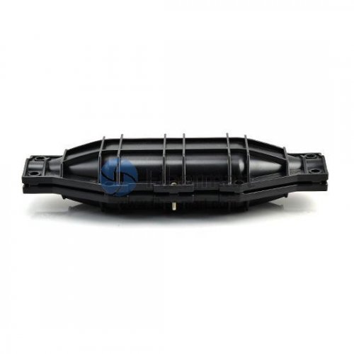
Horizontal Types

Horizontal types splice closure look like a flat or cylindrical box which provide space and protection for fiber optic cable splicing and joint. They can be mounted aerial, buried, or for underground applications. Most horizontal fiber optic splice closure can fit hundreds of fiber connection. They are designed to be waterproof and dust proof. They can be used in temperature ranging from -40°C to 85°C, can accommodate 70 to 106 kpa pressure and the case are usually made of high tensile construction plastic.
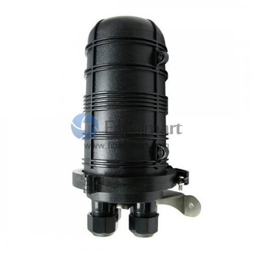
555-111

Vertical Types

Vertical type of fiber optic splice closure looks like a dome. This is why they are also called dome type. They meed the same specification as the horizontal types. They are usually designed for buried applications.

5555555-22222


Conclusion

Fiber-Mart supplies two types of fiber splice closures which are the horizontal (inline) type and the vertical (dome) type. Both are made of excellent engineering plastics to be waterproof and dust proof. And with various ports types, they can fit different fiber optic core numbers.Fiber splice tray, fiber distribution box and fiber optic enclosure are also offered in conjunction with the splice closures, promoting a safe and well-managed environment for fiber optic splices. Custom service is available according to your requirement.any question pls feel free to contact us at service@fiber-mart.com

How to Install Patch Panel and Switch?

by http://www.fiber-mart.com

Patch panel and Ethernet switch are commonly used to connect all devices in data centers. They are usually mounted on the sever rack to perform the revelent functions. Many people are distressed by the installation of patch panel and switch in their telecommunication room, and crazy about the cable spaghetti from the patch panel to switch. In practice, an ideal cable management system could deal with this embarrassing situation. Consequently, a well-designed structured cabling system is in place.
cable management for patch panel and switch
Patch Panel vs. Switch
From physical appearance, patch panel and switch look similar in that they present as rows of sockets in a rack. In fact, a patch panel is a passive device that has a row of ports, which is used for cable management to bundle multiple network ports together to connect incoming and outgoing cables. The ability to label individual cable runs in a patch panel creates a clean and organized way of identifying signal flow and troubleshooting technical problems. On the other hand, a network switch has a bunch of Ethernet ports, but it is an active device that connects devices together on a computer network by using packet switching to receive, process, and forward data to the destination device. In the case of structured cabling, the switch ports can be connected with the ports on the patch panel, allowing the Ethernet devices to be networked together.
Installation Steps for Patch Panel and Switch
Step 1: Determine where to place the patch panel and switch.
The proper operating environment keeps the equipment operate and maintain well. The airflow and vents should be unrestricted.
Step 2: Make up the patch cables of desired length, and indicate how many cables you need.
The slack cables will increase the cost of material and installation, and not facilitate cable management.
Step 3: Map out which switch port is connected to which patch panel port. (How power cables are routed should be considered.)
This delicate movement will cut down the time of whole installation process.
Step 4: Attach the patch panel and switch to a rack-mounted floor stand in the wiring closet.
The rack should accommodate the size of the patch panel and switch (standard 19″ wide is often used.)
Step 5: Run the prepared cables to connect switch port to the patch panel port respectively.
These cables can be moved from port to port if needed to facilitate location changes to the network.
Step 6: Install horizontal and vertical cable management, and Velcro cable ties to bundle the cables together for easier access in the future.
Step7: Labeling each cable with the same tag on both ends.
You can match end-to-end connectivity when you run across all of the ports of the patch panel and switch, which can help you to identify the cables for troubleshooting.
Cable Management from Patch Panel to Switch
Horizontal cable management can be used to support a pathway for patch cables between the patch panel and switch. The horizontal cable management panel has various style for multiple applications: designed with lacing bar, D-rings, finger duct, brush strip, and end ring. They can be assembled randomly to simplify cabling efficiently. The following video shows the 1U horizontal cable manager with end rings manager to neat and clean the messy rack.
Vertical cable management also addresses today’s cable routing demands. 3” single D-ring vertical cable manager and 3” wide plastic vertical cable manager with bend radius fingers are most commonly used between the patch panel and switch. They help to provide proper bend radius support for cables. Come with cable ties, it provides users with a neat and organized cabling system.
Cable Ties & Cable Labels
Cable ties and cable labeling can also help make the installation efficient. When a network system is constructed, large amounts of cables are built into the rack and routed where they need to go with devices. The Velcro cable ties are the most common tools for holding cables together. Meanwhile, cable labels can provide facilities with many benefits that will help increase efficiency, eliminate waste, improve safety, and generally make everything run more smoothly.
Conclusion
Patch panel and switch allow for expansion of traceable access points, which provides a robust and reliable management solution. Therefore, a proper installation for patch panel and switch plays a decisive role in the whole cable management. From patch panel to switch, a comprehensive line of cable management tools is used for protecting and supporting cables. For more information, please visit http://www.fiber-mart.com.

Best Patch Panel Cable Management Techniques

by http://www.fiber-mart.com

In the structured cabling system, a complete connectivity comprises of cable, patch panel, wall outlet and patch cord supporting all LAN applications. Numbers of cables come into or go out, in this situation where easily causes cable spaghetti. A patch panel not only performs the function of acting as the connectors, but also helps to arrange the cables in organized orders. Consequently, the well-organized patch panel cable management provides a reliable cabling system for all of today’s network applications and future-proofing networks.
Why Need Patch Panel Cable Management?
The most part is that a patch panel provides a centralized location to manage network connections. When it comes to making a move, add, or change (MAC), the patch panel cable management would effectively reduce the time and cost to perform physical changes at a patch panel in a wiring closet. Except that, it provides physical security for sensitive network connections (such as fiber links), and minimizes network downtime by allowing easy access during routine maintenance. As a last point, it provides the scalability to increase density when you need to connect a large number of devices.
patch panel cable management
High-Density Cable Management Solutions Based on Patch Panel
Patch panel cable management is involved in many components: fiber optic enclosures (wall mount or rack mount enclosure), fiber optic patch panel (LC, SC, ST, MTP, MPO), fiber optic cassette, horizontal or vertical cable management panel or cable manager. Different kinds of combinations meet the demand to effectively manage high-density structured cabling in different applications.
(1) Rack Mount Enclosure + Fiber Patch Panel
The rack mount enclosure is always loaded with LC, SC, ST, MTP/MPO fiber adapter panel to provide a pathway to connect backbone-to-backbone or backbone-to-horizontal fiber cabling. According to the application demands, different units of fiber enclosure can be selected. Generally, 1U rack enclosure can allow for 4 FAPs up to 96 fibers, 2U up to 192 fibers, and 4U up to 288 fibers. For higher cabling density, the combination of fiber enclosure and fiber patch panel provides an efficient, flexible and easy way for fiber cable management in the data center.
Rack Mount Enclosure + Fiber Patch Panel
(2) Rack Mount Enclosure + Fiber Optic Cassette
In addition to mounting with fiber optic patch panel, rack mount enclosure can also hold MTP-8, MTP-12, or MTP-24 fiber cassette to provide the interface between the MTP connector on the trunk and the LC duplex jumpers for quick connection of remote or data center applications. This mounting option is suitable for 10G to 40G or 25G to 100G application.
 Rack Mount Enclosure + Fiber Optic Cassette
(Note: Wall mount patch panel performs the similar work principles as rack mount patch panel, mounting fiber adapter panel and cassette.)
(3) Blank Rack Mount Modular Panel + Fiber Optic Cassette
The blank modular panel has multiple functions to provide a complete solution for routing network cabling and protecting patch cords. When 1U rack mount modular fiber enclosure panel is mounted with 4 MTP/MPO cassette, it can house the total fiber capacity up to 96 fibers. It is uniquely designed for both front and rear-mounting capabilities with easy-access cable management.
Blank Rack Mount Modular Panel + Fiber Optic Cassette
(4) Blank Rack Mount Modular Panel + Fiber Patch Panel
Except for fiber cassette, the blank rack mount modular panel with lacing bar can also hold 1U fiber patch panel to efficiently manage high-density structured cabling in data centers.
Blank Rack Mount Modular Panel + Fiber Patch Panel
(5) MTP/MPO-LC Enclosure + Cable Management Panel
The MTP/MPO-LC enclosure is designed to connect 40/100G equipment with the existing 10G equipment in a cost-effective way. The breakout panel integrates the benefits of MPO pre-terminated breakout cabling and compact patch panels, and several groups links are dispatched in the distribution box that ensures a high-performance and reliable straight connection from 10 GbE to 40/100 GbE. The cable management panel with D-rings is used for horizontal cable management in the front of 40/100G breakout panel. This solution is perfect for 40/100G migrations in a high-density data center.
MTP MPO-LC Enclosure + Cable Management Panel
(6) Blank Multimedia Adapter Patch Panel + Cable Management Panel
Blank multimedia adapter patch panel allows customization of installation for multimedia applications requiring integration of fiber patch cables and copper cables. The inserted keystone jacks or couplers can be Cat6a, Cat6, Cat5e or Cat5. And the fiber optic adapters can be standard LC duplex, SC simplex, and MTP/MPO. So it can aggregate up to six different types of ports on demand at one time. The cable management panel with D-rings is a kind of cable organizer to keep the cables in an acceptable condition and satisfy the functional requirements of high-density network cabling.
Blank Multimedia Adapter Patch Panel + Cable Management Panel
(7) Ethernet Patch Panel + Horizontal Cable Manager with D-rings
Ethernet patch panel includes Cat5e, Cat6, or Cat7 patch panel. They are an ideal method to create a flexible, reliable and tidy cabling system for Ethernet cables. The horizontal cable manager is often used to arrange small bundles of patch cables from network switches and patch panels. It provides an economical and superior cable management solution for organizing patch cords and maintaining required bend radius.
Ethernet Patch Panel + Horizontal Cable Manager with D-rings
Conclusion
Today’s data centers require a reliable, scalable, and manageable cabling infrastructure, and then the patch panel cable management solutions address these trends and facilitate the efficiency of high-density data center cabling. By the way, when purchasing the cabling infrastructure, there is no single solution that will meet all of the cable management needs. Hope this article provides you with the comprehensive patch panel cable management techniques for the successful cabling deployment in your data center.

How To Repair the Accidentally Cut Fiber Optic Cable?

by http://www.fiber-mart.com

Fiber optic cable can be accidentally damaged, cut or smashed. According to the Electronic Technicians Association, one of the main cause of optical fiber failure is “backhoe fade” , during which the optical fiber cable is cut or damaged while digging. For this occasion, you can easily look for backhoe and get the cut cable. However, if it is caused by moles, it will likely be difficult to troubleshoot it. On the flip side, it means that the cost to repair fiber optic cable might be a little bit expensive because of the equipment involved. Here are a few tools and steps suggested for you to repair broken fiber optic cable.
(1) OTDR (Optical Time Domain Reflectometer)
The OTDR is widely used for the measurement of fiber length, transmission attenuation, joint attenuation and fault location. For more information about OTDR, please refer to Working Principle and Characteristics of OTDR.
OTDR
(2) Fiber Optic Cutter / Stripper
Fiber optic cable cutter and fiber optic stripper are important tools in the fiber optic splicing and some other fiber optic cable cutting applications.
Fiber optic cable cutter and fiber optic stripper
(3) High Precision Fiber Optic Cleaver
Fiber optic cleaver is used to cut the fiberglass for fusion splicing, also ideal for preparing fiber for pre-polished connectors to make a good end face. So it is very important in the fiber splicing process, and it usually works together with the fusion splicer to meet the end needs.
High Precision Fiber Optic Cleaver
(4) Fusion Splicer
Fiber optic fusion splicer may be the act of joining two optical fibers end-to-end using heat. The machine is to fuse both the fibers together in such a way that light passing with the fibers is not scattered or reflected back from the splice.
Fusion Splicer
Steps to Repair Fiber Optic Cable
Step 1: Use OTDR to Identify the Break in Fiber Optic Cable
The first thing you need to do is to look for the break in your fiber optic cables. Commonly, the fiber-optic technicians utilize a device which is known as an OTDR. With the ability to work like radar which sends a light pulse right down to the optical fiber cable. It will be deflected to your device when it encounters break. It helps technician know the position of the break.
Step 2: Use Fiber Optic Cutter to Cut Out the Damaged Fiber Optic Cable
After knowing the location of the break, you should dig up the fiber optic cables with the break. The fiber optic cutter is used to cut out the damaged section.
Step 3: Strip the Fiber Optic Cable by Fiber Optic Stripper
You should use fiber optic stripper to strip the fiber on the both end and peel the jacket gently to expose the fiber-optic tube inside. Then, cut any sheath and yarn by fiber optic cutting tools.
Strip the Fiber Optic Cable by Fiber Optic Stripper
Step 4: Trim Any Damage on the Optical Fiber Ends by High Precision Fiber Cleaver
The following picture lists the main 6 steps for fiber cleaving by high precision fiber cleaver.
6 steps for fiber cleaving by high precision fiber cleaver
Step 5: Clean the Striped Fiber Optic Cable
This step is crucial to ensure that your terminal will get a clean wire strip. You have to clean the stripped fiber with alcohol and lint-free wipes. Ensure that the fiber doesn’t touch anything.
Step 6: Splice the Fiber Optic Cable
Generally, there are two methods to splice optical fiber cable: (1) mechanical splicing; (2) fusion splicing.
(1) Mechanical Splicing
If you want to produce a mechanical connection, you need to put inline splice quick-connect fiber-optic connectors to the fiber. Hold the two fiber ends in a precisely aligned position thus enabling light to pass from one fiber into the other. (Typical loss: 0.3 dB)
(2) Fusion Splicing
In fusion splicing, a fusion splicer is used to precisely align the two fiber ends. You have to convey a fusion splice protector to the fiber, and place the fibers which is spliced within the fusion splicer. Then, the fiber ends are “fused” or “welded” together using some type of heat or electric arc. This produces a continuous connection between the fibers enabling very low loss light transmission. (Typical loss: 0.1 dB)
Step 7: Perform the Connection Test of Fiber Optic Cable with OTDR
The very last thing would be to see the connection of fiber-optic using the OTDR. Then put back those splices into the splice enclosure. Close the enclosure after which rebury the fiber optic cables.

Understanding of FTTx Network

FTTx technology plays an important role in providing higher bandwidth for global network. And FTTx (fiber to the x) architecture is a typical example of substituting copper by fiber in high data rate traffic.

FTTx technology plays an important role in providing higher bandwidth for global network. And FTTx (fiber to the x) architecture is a typical example of substituting copper by fiber in high data rate traffic.According to the different termination places, the common FTTx architectures include FTTH, FTTB, FTTP, FTTC and FTTN. This article will introduce these architectures respectively.


What is FTTx Network?

FTTx, also called as fiber to the x, is a collective term for any broadband network architecture using optical fiber to provide all or part of the local loop used for last mile telecommunications.


Different FTTx Architectures

FTTP: fiber-to-the-premises, is a loosely used term, which can encompass both FTTH and FTTB or sometimes is used a particular fiber network that includes both homes and businesses. It depends on how the context is used and specific location of where the fiber terminates. FTTP can offer higher bandwidth than any other broadband services, so operators usually use this technology to provide triple-play services.

FTTH: as indicated by the name fiber-to-the-home, fiber from the central office reaches the boundary of the living space, such as a box on the outside wall of a home. Once at the subscriber’s living or working space, the signal may be conveyed throughout the space using any means, such as twisted pair, coaxial pair, wireless, power line communication, or optical fiber. Passive optical networks (PONs) and point-to-point Ethernet are architectures that deliver triple play services over FTTH networks directly from a operator’s central office.

FTTB (fiber to the building) — Fiber terminates at the boundary of the building. A fiber cable in FTTB installation goes to a point on a shared property and the other cabling provides the connection to single homes, offices or other spaces. FTTB applications often use active or passive optical networks to distribute signals over a shared fiber optic cable to individual households of offices.

FTTC( fiber-to-the curb or -cabinet), is a telecommunication system where fiber optic cables run directly to a platform near homes or any business environment and serves several customers. Each of these customers has a connection to this platform via coaxial cable or twisted pair. The term “curb” is an abstraction and just as easily means a pole-mounted device or communications closet or shed. Typically any system terminating fiber within 1000 ft (300 m) of the customer premises equipment would be described as FTTC. A perfect deployment example of FTTC is a DLC/NGDLC (digital loop carrier) which provides phone service.

FTTN (fiber to the node) — Fiber terminates in a street cabinet, which may be miles away from the customer premises, with the final connections being copper. One of the main benefits of FTTN is the ability to deliver data over more efficient fiber optic lines, rather than other fiber optic lines with greater speed restriction


Conclusion

The advent of FTTx network is of great significance for people around the world. As it has a higher speed, costs less, and carries more capacity than twisted pair conductor or coaxial cables. Fiber-Mart can provide customized service ,pls don’t hesitate to contact me at service@fiber-mart.com

Loose Tube Cables In Outdoor Applications

Fiber optic cables are constructed in two ways: Loose Tube and tight buffered.and Loose tube optical cable designs are optimized for outside plant applications and have demonstrated over 20 years of proven field performance.

Fiber optic cables are constructed in two ways: Loose Tube and tight buffered.and Loose tube optical cable designs are optimized for outside plant applications and have demonstrated over 20 years of proven field performance.


Features

Loose tube cables are designed for harsh environment conditions in the outdoors. They protect the Fiber core, cladding, and Coating by enclosing everything within fairly rigid protective sleeves or tubes. Many loose tube cables contain a water resistant Gel surrounding the fibers. The gel helps protect the fibers from moisture, making the cables ideal for high humidity environments, where water or condensation may otherwise be problematic. The gel filled tubes can expand or contract with temperature changes, as well. Despite the benefits, gel filled loose tube cables are not the right choice if the Cable needs to be submerged in water, or routed around multiple bends. Excess Strain may cause the fibers to emerge from the gel. Tight buffered cables are optimal for indoor applications. Being more robust than loose-tube cables, they are best suited for moderate length LAN or WAN connections, long indoor runs, direct burial, and for underwater use. Rather than using the gel Layer loose tube has, tight buffered cables have a two-layer coating. The first is plastic, and the other, waterproof acrylate. The Acrylate keeps moisture away from the cable. The Core is never exposed when bend or compressed underwater. Tight buffered cables may be easier to install, because there is no gel to clean up and it does not require a fan out kit for Splicing or termination.


Application

. Usable for ducts, direct burial, aerial installation
. Long distance communication system
. Subscriber network system
. Local area network system


Waterblocking requirement

loose tube fiber optic cable is designed to provide maximum protection against water penetration and water migration by utilizing intrusion preventative measures in both the cable core and the buffer tubes. Water-blocking protection of the cable core is accomplished by surrounding it with a dry water-swellable tape and yarns, or with a gel, to stop the entry and migration of water should the cable’s outer jacket be breached. This protective measure is included primarily to maintain the mechanical integrity of the cable itself (e.g. prevent ice crush from within the cable, fungus growth, or corrosion of metallic cable members when present). The water-blocking protection, water-swellable yarn or gel, is placed in the buffer tubes with the optical fiber during manufacture of the cable.

056c220ec3fa39da65c34fb967a9e6aa.image.500x500

Standard

The predominant users of outside plant cable continue to specify loose tube cables in outdoor environments. Loose tube cables must pass rigorous mechanical, environmental and optical tests in accordance with accepted Electronic Industries Association/Telecommunications Industry Association (EIA/TIA) fiber optic test procedures (FOTPs). Loose tube cables are specifically designed to perform in harsh outdoor environments with minimal performance degradation. a new standard, ICEA S-104-696, “Standard for Indoor – Outdoor Optical Fiber Cables” has been developed which addresses the need for an inter-building and intrabuilding cable. These cables can be loose tube or tight buffered for the ease of termination such as premises cable, but must offer the tensile strength, waterblocking protection, and UV protection of an outside plant cable. These inter-/intrabuilding cables are typically used for short runs to connect to another building(s) and some limited premises applications.


Summary

Optical cables are designed to protect the optical fibers from damage due to the rigors of installation and from the demands of the surrounding environment. Fiber-Mart provides a wide range of quality optical fiber cables with detailed specifications displayed for your convenient selecting. Per foot price of each fiber cable is flexible depending on the quantities of your order, making your cost of large order unexpected lower. Customers can also have the flexibility to custom the cable plant to best fit their needs. Only fiber cable that meets or exceeds industry standards is used to ensure quality products with best-in-class performance. Any question pls feel free to contact me at service@fiber-mart.com