What is An Optical Module?

An optical transceiver chip is an integrated circuit (IC) that transmits and receives data using optical fiber rather than electrical wire. Optical fiber, also called fiber optic, refers to the technology associated with the transfer of information in light beams or pulses along solid transparent fibers or cables. optical transceiver chips facilitate the use of fiber to the premises (FTTP) services, in which optical fiber runs from central hubs all the way to the end users. This can provide extremely high-speed Internet access. Optical fiber systems can also be used to transmit and receive telephone communications and to receive digital television broadcasts.


Fiber Optic Transceivers Modules


An optical fiber transceiver is also called fiber optic transmitter and receiver, the function of the optical module is photoelectric conversion. The transmitter end takes in and converts the electrical signal into light, after the optical fiber transmission in the fiber cable plant, the receiver end again converts the light signal into electrical signal. Both the receiver and the transmitter ends have their own circuitry and can handle transmissions in both directions.


Types


There are a number of different  types of  fiber optic transceivers available in the market. They differ in the type of connections, data transmission speed, as well as packing forms. According to the package, common type of fiber optic transceivers popular in the market is SFP, SFP+, XFP, X2, Xenpak, GBIC. According to the fiber type it connect to, there are MM (multimode), SM (Single mode), as well as WDM fiber (CWDM, DWDM modules).

Single Mode vs. Multimode Optical Modules: How Do You Choose?


Transceiver module usually come in either single mode or multimode modules. Chances are that you may make a choice between these two types transceiver module. But before that, there are a couple of factors you should consider. Single mode transceiver modules support longer reach data transmission and higher speed rates than multimode transceiver module. That’s mainly because multimode modules have shorter wavelength(around 850nm) than single mode modules(around 1260nm-1650nm). But in datacom environments, both singlemode transceiver modules and multimode transceiver modules can accommodate speeds beyond 50G as of today. And due to the “fragility” of single mode fiber system, single mode modules usually cost more than multimode. But single mode fiber costs less than multimode fiber. With regard to how to save largest budget, read this article for cost comparison: Single-mode Cabling Cost vs. Multimode Cabling Cost. So if you are hovering over the two types, port speed, desired reach and interconnect topology and total cost should be considered as the main decision criteria.


Can Single Mode Optical Modules Connect to Multimode Optical Modules?


The short answer for this question is no. Single mode module is 1310nm laser-based, and multimode module is 850nm LED-based, therefore, single mode optical modules only work over single mode fiber and multimode optical modules only work over multimode fiber. Single mode module should be used with single mode module over single mode fibers, and multimode module should be used with multimode module over multimode fibers. We can’t connect single mode module to multimode module. But for some optical modules that can work both over single mode and multimode fibers, such as 1310nm laser-based 1000BASE-LX/LH modules.


Conclusion


With the rapid development of Internet service and communication industry, optical communication is bound to become the most important strategic industry in 21th century. The elementary components of a basic optical communication consists of Ethernet switch, WDM passive device, optical module etc. Optical modules are the key building blocks for all network connectivity both inside and outside the data center. Fiber-Mart manufactures and supplies a complete range of optical modules which can be Customized. for more information, welcome to visit www.fiber-mart.com or contact me by e-mail: service@fiber-mart.com

What is an Optical Module?

An optical transceiver chip is an integrated circuit (IC) that transmits and receives data using optical fiber rather than electrical wire.


An optical transceiver chip is an integrated circuit (IC) that transmits and receives data using optical fiber rather than electrical wire. Optical fiber, also called fiber optic, refers to the technology associated with the transfer of information in light beams or pulses along solid transparent fibers or cables. optical transceiver chips facilitate the use of fiber to the premises (FTTP) services, in which optical fiber runs from central hubs all the way to the end users. This can provide extremely high-speed Internet access. Optical fiber systems can also be used to transmit and receive telephone communications and to receive digital television broadcasts.


Fiber Optic Transceivers Modules


An optical fiber transceiver is also called fiber optic transmitter and receiver, the function of the optical module is photoelectric conversion. The transmitter end takes in and converts the electrical signal into light, after the optical fiber transmission in the fiber cable plant, the receiver end again converts the light signal into electrical signal. Both the receiver and the transmitter ends have their own circuitry and can handle transmissions in both directions.

200

Types

There are a number of different  types of  fiber optic transceivers available in the market. They differ in the type of connections, data transmission speed, as well as packing forms. According to the package, common type of fiber optic transceivers popular in the market is SFP, SFP+, XFP, X2, Xenpak, GBIC. According to the fiber type it connect to, there are MM (multimode), SM (Single mode), as well as WDM fiber (CWDM, DWDM modules).


Single Mode vs. Multimode Optical Modules: How Do You Choose?

Transceiver module usually come in either single mode or multimode modules. Chances are that you may make a choice between these two types transceiver module. But before that, there are a couple of factors you should consider. Single mode transceiver modules support longer reach data transmission and higher speed rates than multimode transceiver module. That’s mainly because multimode modules have shorter wavelength(around 850nm) than single mode modules(around 1260nm-1650nm). But in datacom environments, both singlemode transceiver modules and multimode transceiver modules can accommodate speeds beyond 50G as of today. And due to the “fragility” of single mode fiber system, single mode modules usually cost more than multimode. But single mode fiber costs less than multimode fiber. With regard to how to save largest budget, read this article for cost comparison: Single-mode Cabling Cost vs. Multimode Cabling Cost. So if you are hovering over the two types, port speed, desired reach and interconnect topology and total cost should be considered as the main decision criteria.


Can Single Mode Optical Modules Connect to Multimode Optical Modules?

The short answer for this question is no. Single mode module is 1310nm laser-based, and multimode module is 850nm LED-based, therefore, single mode optical modules only work over single mode fiber and multimode optical modules only work over multimode fiber. Single mode module should be used with single mode module over single mode fibers, and multimode module should be used with multimode module over multimode fibers. We can’t connect single mode module to multimode module. But for some optical modules that can work both over single mode and multimode fibers, such as 1310nm laser-based 1000BASE-LX/LH modules.


Conclusion

With the rapid development of Internet service and communication industry, optical communication is bound to become the most important strategic industry in 21th century. The elementary components of a basic optical communication consists of Ethernet switch, WDM passive device, optical module etc. Optical modules are the key building blocks for all network connectivity both inside and outside the data center.Fiber-Mart manufactures and supplies a complete range of optical modules which can be Customized. for more information, welcome to visit www.fiber-mart.com or contact me by e-mail: service@fiber-mart.com

How much do you know about MTP/MPO ?

With widespread deployment of 40G and 100G networks, high-density MTP/MPO cable solutions are also become more and more popular. Unlike traditional 2‐fiber configurations LC or SC patch cords, with one send and one receive, 40G & 100G Ethernet implementations over multimode fibers use multiple parallel 10G connections that are aggregated.

With widespread deployment of 40G and 100G networks, high-density MTP/MPO cable solutions are also become more and more popular. Unlike traditional 2‐fiber configurations LC or SC patch cords, with one send and one receive, 40G & 100G Ethernet implementations over multimode fibers use multiple parallel 10G connections that are aggregated. 40G uses four 10G fibers to send and four 10G fibers to receive, while 100G uses ten 10G fibers in each direction. MTP/MPO cable can hold 12 or 24 fibers in a connector, which greatly facilitates the upgrade to 40G and 100G networks. However, since there are so many fibers, the polarity management of the MTP/MPO cable may be a problem.

What is MTP/MPO Cable Assembly?

The core of MTP/MPO fiber assembly lies in its connector—MTP/MPO connector. MTP/MPO connector factory terminated assembly can house 6 to 72 fibers, with 12-fiber and 24-fiber arrays being the most common. MTP/MPO connector is available in a male version (with pins) or a female version (without pins). The pins ensure that the fronts of the connectors are exactly aligned on contact and that the endfaces of the fibers are not offset. There are guide grooves (keys) on the top side of the factory terminated MTP/MPO connector, which ensures that the adapter holds the connector with the correct ends aligned with each other. The push-pull design of MTP/MPO connector facilitates easier insertion and removal, making it a breeze when using with QSFP+ transceiver modules in 40/100G network.

1

What is MTP Modules and Harnesses ?

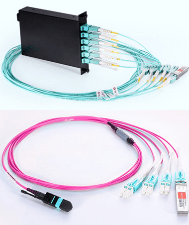
An obvious benefit to deploying a MTP-based optical network is its flexibility to transmit both serial and parallel signals. MTP to duplex connector transition devices such as modules and harnesses are plugged into the MTP trunk assemblies for serial communication. MTP Modules are typically used in lower-portcount break-out applications such as in server cabinets. MTP harnesses provide a significant increase in cabling density and find value in high port count break-out situations such as SAN Directors . The built-in modularity of the solution provides flexibility to easily configure and reconfigure the cabling infrastructure to meet current and future networking requirements. MTP harnesses and modules can be exchanged or completely removed from the backbone network to quickly adapt to data center MACs.

图片1444

MTP Modules in Data Centers

MTP modules typically are placed in a housing located in the cabinet rack unit space. Here the MTP trunk cable is plugged into the back of the module. Duplex patch cords are plugged into the front of the module and routed to system equipment ports. Integrating the MTP modules cabling solution into the data center cabinet can enhance the deployment and operation of the data center cabling infrastructure. As shown in the figure below, integrating the MTP modules into the cabinet vertical manager space maximizes the rack unit space available for data center electronics. MTP modules are moved to the cabinet sides where they snap into brackets placed between the cabinet frame and side panel. Properly engineered solutions will allow MTP modules to be aligned with low-port-count system equipment placed within the cabinet rack unit space to best facilitate patch cord routing.

MTP Harnesses in Data Centers

MTP harnesses are plugged into the backbone MTP trunk assemblies through an MTP adapter panel. The MTP adapter panel is placed in a housing that is also typically located in the cabinet rack unit space. MTP to LC 12-fiber break-out harnesses plug into the front of the adapter panels and are routed over to the director line cards where the LC duplex ends are plugged into the line card ports. These MTP harnesses are pre-engineered to a precise length with strict tolerances to minimize slack, while a small outside diameter allows for easy routing without preferential bend concerns. With a pre-engineered cabling management, not only is installation simplified, but the time required for SAN design and documentation is greatly reduced with port mapping architecture inherent to the design.

What is MTP/MPO Connectors?

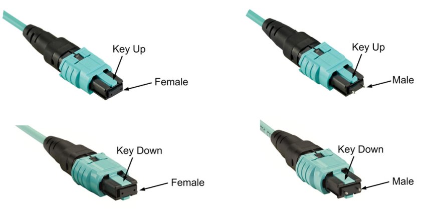
Before explaining the polarity, it is important to learn about the structure of MTP/MPO connector first. Each MTP connector has a key on one side of the connector body. When the key sits on top, this is referred to as the key up position. In this orientation, each of the fiber holes in the connector is numbered in sequence from left to right. We will refer to these connector holes as positions, or P1, P2, etc. Each connector is additionally marked with a white dot on the connector body to designate the position 1 side of the connector when it is plugged in.

11Since the MTP connectors can either key up and key down, there are two types of MPO adapters.

Type A: Key-up to key-down
Here the key is up on one side and down on the other. The two connectors are connected turned 180° in relation to each other.
Type B: Key-up to key-up
Both keys are up. The two connectors are connected while in the same position in relation to each other.

222

Two Polarity of Traditional Duplex Patch Cable

Classic duplex cables are available in a cross-over version (A-to-A) or a straight-through version (A-to-B) and are terminated with LC or SC connectors. Telecommunications Cabling Standard defines the A-B polarity scenario for discrete duplex patch cords, with the premise that transmit (Tx) should always go to receive (Rx) — or “A” should always connect to “B”. Therefore, A-B polarity duplex is very common in applications.

444

Three Polarity of MTP/MPO Multi-Fiber Cable

Unlike traditional duplex patch cables, there are three polarity for MTP/MPO cables: polarity A, polarity B and polarity C.

Polarity A

Polarity A MTP cables use a key up, key down design. Therefore, as shown in the figure below, the position 1 of one connector is corresponding to the position 1 of another connector. There is no polarity flip. Therefore, when we use polarity A MTP cable for connection, we must use A-B duplex patch cables on one end and A-A duplex patch cables on the other end. Since in this link, Rx1 must connect to Tx1. If we don’t use A-A duplex patch cable, according to the design principle of polarity A MTP cable, fiber 1 may transmit to fiber 1, that is to say Rx1 may transmit to Rx1, which may cause errors.
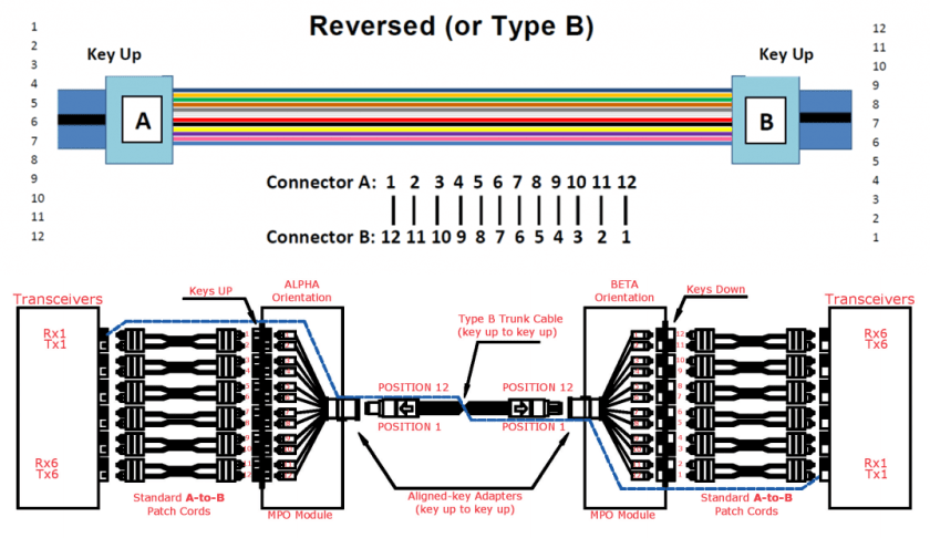
555

Polarity B

Polarity B MTP cables use a key up, key up design. Therefore, as shown in the figure below, the position 1 of one connector is corresponding to the position 12 of another connector. Therefore, when we use polarity B MTP cable for connection, we should use a A-B duplex patch cables on both ends. Since the key up to key up design help to flip the polarity, which makes fiber 1 transmit to fiber 12, that is the Rx1 transmits to Tx1.
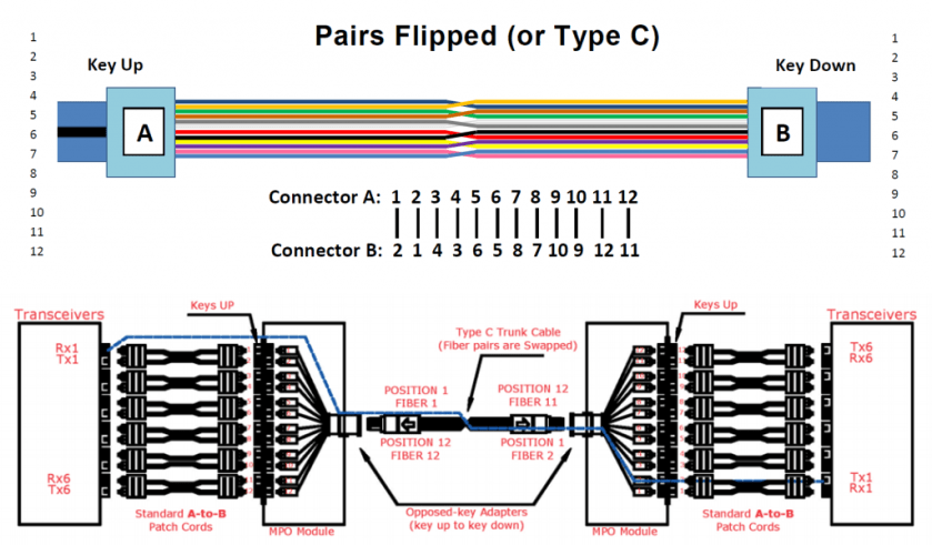
666Polarity C

Like the polarity A MTP cables, polarity C MTP cables also use a key up, key down design. However, within in the cable, there is a fiber cross design, which makes the position 1 of one connector is corresponding to the position 2 of another connector. As shown in the figure below, when we use polarity C MTP cable for connection, we should use a A-B duplex patch cables on both ends. Since the cross fiber design help to flip the polarity, which makes fiber 1 transmit to fiber 2, that is the Rx1 transmits to Tx1.

777

Conclusion

Speed is paramount to a data center, therefore data center are always on the road to higher density data rates. Different polarity MTP cables may have different connection methods. No matter which type cable you choose, remember its design principle and choose the right cabling infrastructure for your network. MTP/MPO fiber optic cable assembly appears to be the best option to improve speed, agility and performance of the system. Considering the time saving, space efficiency and flexibility, it is worthwhile to make MTP/MPO cabling a part of your data center. Fiber-Mart has various MTP/MPO products, If you have any requirement of our products, please contact us: product@fiber-mart.com.

Setting up Fiber Optics Technology

by http://www.fiber-mart.com

It is widely assumed that fiber optics is a new phenomenon that has recently revolutionized the communication infrastructure. Contrary to common belief, Chicago witnessed the first installation of a fiber optic link as far back as 1976. Since then, fiber optics has become widely used in telecommunications because of its large bandwidth and distance advantages over conventional copper wire.
fiber optic patch cords As fiber optic communication users grow, the need to have a highly reliable system becomes more evident. By paying more attention to the design, installation and operation of a fiber optic system, it is possible to take advantage of the security, bandwidth and distance that fiber optics offers. What are some guidelines you can use to ensure proper installation and usage of your fiber optic system? The first step is to determine the distance or the range of the link that you are working with – longer links require singlemode fibers or lasers, while shorter links take multimode fibers or LED Sources.
Then consider the environment you are working with – is your installation outdoors or above the ceiling , or in an office or factory floor. These factors will help to determine how your fiber will be mounted. If you have a ceiling application, you may want to source fiberglass push and pull rods to help you with those hard to reach places.
greenlee pro wire strippersNow it is important to plan splicing requirements, long lengths of cables may need to be spliced and the right tools go a long way to doing a great job. If you’re cutting into tight-buffered cable your best option is to use Kevlar shears because they cut the cable clean and neat which can save polishing time. Another good investment would be cable strippers and lint free wipes to clean any debris left from the glass fibers. You also want to consider the type of hardware that may come in handy, if splice closures are appropriate; these will have to be sourced beforehand.
Once your fibers have been sheared, polished, cleaned and tested it becomes important to choose a termination type appropriate for your application. Remember to clean all your connectors properly and to label all your cables to identify your fiber optic cable. There are now kits on the market that may carry everything you need, which will save you a bit of time in sourcing different tools necessary for your application. Once you have documented your entire fiber optic network you should be good to go. Remember, documentation is foresight; it will help when it comes time to troubleshoot, upgrade or restore your network.

Fiber Optic Fusion Splicers and How They Work

by http://www.fiber-mart.com

What is a fiber optic fusion splicer?
A fiber optic fusion splicer is a device that uses an electric arc to melt two optical fibers together at their end faces, to form a single long fiber. The resulting joint, or fusion splice, permanently joins the two glass fibers end to end, so that optical light signals can pass from one fiber into the other with very little loss.
How does a fusion splicer work?
Before optical fibers can be successfully fusion-spliced, they need to be carefully stripped of their outer jackets and polymer coating, thoroughly cleaned, and then precisely cleaved to form smooth, perpendicular end faces. Once all of this has been completed, each fiber is placed into a holder in the splicer’s enclosure. From this point on, the fiber optic fusion splicer takes over the rest of the process, which involves 3 steps:
Alignment: Using small, precise motors, the fusion splicer makes minute adjustments to the fibers’ positions until they’re properly aligned, so the finished splice will be as seamless and attenuation-free as possible. During the alignment process, the fiber optic technician is able to view the fiber alignment, thanks to magnification by optical power meter, video camera, or viewing scope.
Impurity Burn-Off: Since the slightest trace of dust or other impurities can wreak havoc on a splice’s ability to transmit optical signals, you can never be too clean when it comes to fusion splicing. Even though fibers are hand-cleaned before being inserted into the splicing device, many fusion splicers incorporate an extra precautionary cleaning step into the process: prior to fusing, they generate a small spark between the fiber ends to burn off any remaining dust or moisture.
Fusion: After fibers have been properly positioned and any remaining moisture and dust have been burned off, it’s time to fuse the fibers ends together to form a permanent splice. The splicer emits a second, larger spark that melts the optical fiber end faces without causing the fibers’ cladding and molten glass core to run together (keeping the cladding and core separate is vital for a good splice – it minimizes optical loss). The melted fiber tips are then joined together, forming the final fusion splice. Estimated splice-loss tests are then performed, with most fiber fusion splices showing a typical optical loss of 0.1 dB or less.

1.25mm OD Singlemode Ceramic Ferrule for LC Fiber Connector 1.0um Online Sale

Specification:

Outer diameter: (1.2499±0.0005)mm
Inner diameter: (0.125+0.001/-0)mm
Concentricity: 1.0μm
Insertion loss:≤0.2dB
return loss:≥60dB
length:(6.50±0.05)mm

Features:

Good compatibility
Accurate mechanical dimensions
Good reliability and stability
Compliant with RoHS, Bellcore, IEC

product link: https://www.fiber-mart.com/125mm-od-singlemode-ceramic-ferrule-for-lc-fiber-connector-10um-online-sale-p-16522.html


Application:

Telecommunication
CATV
LAN (including FTTx)
Data network