Remateable connections are made possible by Fiber Connectors. Fiber Connectors are therefore generally used where flexibility is needed at termination points when an optical signal is routed. Examples would include connections from receivers to equipment pigtails, or normal termination, or when re-configuring systems. Remateable connections make it easy to meet changing customer requirements by simplifying system reconfigurations.
Application
Optical fiber connectors are used to join optical fibers where a connect/disconnect capability is required. Due to the polishing and tuning procedures that may be incorporated into optical connector manufacturing, connectors are often assembled onto optical fiber in a supplier’s manufacturing facility. However, the assembly and polishing operations involved can be performed in the field, for example, to terminate long runs at a patch panel.
Optical fiber connectors are used in telephone exchanges, for customer premises wiring, and in outside plant applications to connect equipment and cables, or to cross-connect cables.

Most optical fiber connectors are spring-loaded, so the fiber faces are pressed together when the connectors are mated. The resulting glass-to-glass or plastic-to-plastic contact eliminates signal losses that would be caused by an air gap between the joined fibers.
Performance of optical fiber connectors can be quantified by insertion loss and return loss. Measurements of these parameters are now defined in IEC standard 61753-1. The standard gives five grades for insertion loss from A (best) to D (worst), and M for multimode. The other parameter is return loss, with grades from 1 (best) to 5 (worst).
A variety of optical fiber connectors are available, but SC and LC connectors are the most common types of connectors on the market. Typical connectors are rated for 500–1,000 mating cycles.The main differences among types of connectors are dimensions and methods of mechanical coupling. Generally, organizations will standardize on one kind of connector, depending on what equipment they commonly use.
In many data center applications, small (e.g., LC) and multi-fiber (e.g., MTP/MPO) connectors have replaced larger, older styles (e.g., SC), allowing more fiber ports per unit of rack space and higher data rate application such as 100 Gigabit Ethernet.
Features of good connector design:
- Low insertion loss
- High return loss (low amounts of reflection at the interface)
- Ease of installation
- Low cost
- Reliability
- Low environmental sensitivity
- Ease of use
Outside plant applications may require connectors be located underground, or on outdoor walls or utility poles. In such settings, protective enclosures are often used, and fall into two broad categories: hermetic (sealed) and free-breathing. Hermetic cases prevent entry of moisture and air but, lacking ventilation, can become hot if exposed to sunlight or other sources of heat. Free-breathing enclosures, on the other hand, allow ventilation, but can also admit moisture, insects and airborne contaminants. Selection of the correct housing depends on the cable and connector type, the location, and environmental factors. Careful assembly is required to ensure good protection against the elements.
Depending on user requirements, housings for outside plant applications may be tested by the manufacturer under various environmental simulations, which could include physical shock and vibration, water spray, water immersion, dust, etc. to ensure the integrity of optical fiber connections and housing seals.
what’s the difference of Fiber Connectors?
Given the variety of splice options available to fiber network planners today identifying the best connector for FTTH can be overwhelming. Consequently often not much thought is given to connector selection with choice driven by cost, availability or what’s been used before. However each connector has its own unique design and therefore, pros and cons. Over time or depending on project size this can have a dramatic impact on deployment speeds and costs.

So what are the differences and what do they mean to your implementation? This table of common connectors gives an overview of strengths and weaknesses, with more detail in the accompanying descriptions:
1.Standard Connector (SC)
Simple, rugged and low cost, SC connectors use a ceramic ferrule to deliver accurate alignment of the SMF. The SC connector comes with a locking tab that enables push on / pull off operation.
At the time of writing the most popular choice for such equipment like Fiber Multiplexers, GPON and EPON ONU’s, Fiber Media Converters and more.
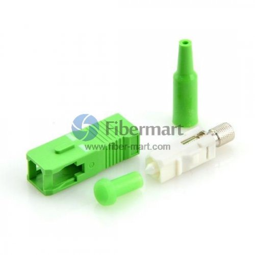
Figure 3: SC connector
2.Ferrule Core Connector (FC)
Although the FC connector was widely used in fiber optic networks until of late, its use is dwindling fast. This connector uses a threaded container and a position locatable notch to achieve exact locating of the SMF in relation to the receiver and the optical source. Once the connector is installed, its position is maintained with total precision.
FC connector is pretty common choice for example in Video over Fiber Transmission Equipment.
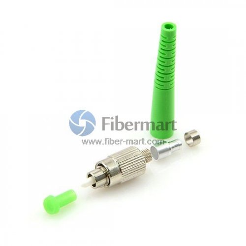
Figure 4: FC connector
3.Lucent Connector (LC)
The Lucent Connector, sometimes referred to as the Little Connector, is a small form factor FOC that uses a 1.25 mm ferrule. There are 3 different types of LC connectors:
- Single Mode LC APC
- Single Mode LC UPC
- Multi-Mode LC UPC
If you had used any SFP module, you have sure seen this connector.

Figure 5: LC connector
LC connector is always present on SFP’s, and if some equipment uses SFP as transmitter, like for example our USB over fiber transmitters, then you can recognize it easily.
4. ST Connector
The ST connector’s keyed bayonet design is similar to that of a BNC (Bayonet Nut Connector or Bayonet Neill-Concelman) connector. The connector is used widely for MMF and SMF FOC and is extremely easy to use. The ST connector is manufactured in two versions – the ST and the ST-II. Both types are keyed and spring loaded, and use a “push-in and twist” mechanism.

Figure 6: ST connector
In some cases, if Multimode type cable is required, some of our customers order RCA audio over fiber converter, with ST connectors:
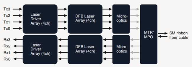
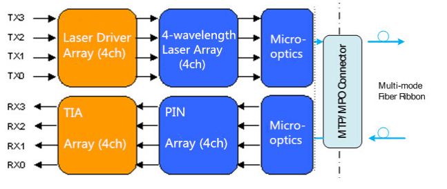
5. MTP/MPO connector
The MT ferrule connector is another of NTT’s inventions and has been around since the 1980s, although the technology has only recently become popular under branded versions of the Multiple Fiber Push-On/Pull-Off connector, such as MTP and MPO. It is larger than the other connectors but for good reason – it can support up to 24 fibers in a single ferrule.
Multi-fiber connectors are not currently designed for field-fit applications so must be lab terminated. In high density patch environments such as datacenters they are used extensively, both at single mode and multi-mode wavelengths. On a ‘per-fiber’ basis the costs are relatively inexpensive. However as might be expected, the attenuation loss can be higher than a single ceramic ferrule connector. That being said, it is possible to order ‘low loss’ MTP/MPO connectors which have comparable insertion loss performances. These are more costly however.
Network planners should also consider that whilst still using a uniter/adaptor much like other connectors, the MTP/MPO must also be mated to an opposing male or female connector. This may require more than one connector specification or type within inventory, adding to cost and complexity.
Because the sequence of the fibers cannot physically be changed after termination, the connector is often supplied with a fan-out assembly at the opposing end (such as LC, SC FC etc.). This allows the operator to change channels simply by re-patching the fanned-out side of the cable. The consequence of this is that the small form high density design of the MTP/MPO will only benefit one side of the assembly.
Fiber-Mart can supply many kinds fiber connectors. If you have any questions or requirement of fiber connectors,welcome to contact us: product@fiber-mart.com.