How To Make Fiber Optic Patch Cables

by http://www.fiber-mart.com

Times are tough these days, which is why many people are looking to save a few dollars any way they can. A couple weeks ago we made a video showing you How To Build an Inexpensive Wall Mount Fiber Box. We’ve already had quite a few customers thank us for that cost saving solution. Today, let’s talk about making your own fiber optic patch cables.
Seems like just about everyone in the low voltage industry has made their own ethernet cat5e/cat6 cables at least once in their life (me included). And I’m sure you have too. So you’re thinking, those are really easy and only take a few minutes, why don’t I just start making my own fiber cables. Unfortunately, we’re not comparing apples to apples here. Making your own fiber cables CAN be an easy process, but it’s not very economical. I’m talking about the FAST fiber connectors from AFL Telecommunications. Although these connectors require only a couple minutes per strand to complete, they are much pricier than regular connectors and still require a couple expensive tools. It wouldn’t make sense to buy these unless you already had the tools and did fiber terminations regularly. Even then, the cost of the connectors make this an expensive way to make fiber jumpers. If this is still something your interested in, watch the video below.
The other option for making fiber cables would be epoxy fiber connectors. These connectors have been around for quite a while now and are fairly inexpensive. The problem with these connectors is the amount of time involved in terminating them. In addition, you still need all the tools and testing equipment to get the job done. Well, I thought you were going to show us how to make fiber jumpers? That’s where the “kinda” comes in. Watch the video below for a brief explanation on making fiber cables, but when it comes down to it, buying pre-made fiber cables is the way to go. You can order them in any length you need, with any type of fiber, and any type of connector. If you need more than 2 strands of fiber, or plan on using them for a long distance, I would recommend Pre-Terminated Fiber Optic Cable. Pre Terminated fiber assemblies are just like the fiber jumpers, but can be pulled long distances and are much more durable. To order any of the products talked about in this article, simply click the links above or visit fiber-mart.com.

Multimode Fiber Optic Patch Cable Overview

by http://www.fiber-mart.com

We know that fiber optic patch cables play a very important role in the connection between devices and equipment. When talking about fiber optic patch cables, we usually divide them into multimode fiber optic patch cables and singlemode fiber optic patch cables according to the modes of the cable. What is multimode fiber optic patch cable? How many types of multimode patch cables are there? And what is the difference between multimode and singlemode patch cables? What are the applications of multimode patch cables? This text will solve those questions one by one.
Introduction
Multi-mode fiber patch cables are described by the diameters of their core and cladding. There are two different core sizes of multi-mode fiber patch cords: 50 microns and 62.5 microns. Both 62.5 microns and 50 microns patch cable feature the same glass cladding diameter of 125 microns. Thus, a 62.5/125µm multi-mode fiber patch cable has a 62.5µm core and a 125µm diameter cladding; and a 50/125µm multi-mode fiber patch cable has a 50µm core and a 125µm diameter cladding. The larger core of multi-mode fiber patch cords gathers more light and allows more signals to be transmitted, as shown below. Transmission of many modes of light down a multi-mode fiber patch cable simultaneously causes signals to weaken over time and therefore travel short distance.
Types of Multimode Fiber Optic Patch Cable
Multimode fiber optic cables can be divided into OM1, OM2, OM3, and OM4 based on the types of multimode fiber. The letters “OM” stands for optical multimode. OM1 and OM2 belong to traditional multimode fiber patch cable, while OM3 and OM4 belong to the new generation fiber patch cable which provides sufficient bandwidth to support 10 Gigabit Ethernet up to 300 meters. The connector types include LC, FC, SC, ST, MU, E2000, MPO and so on. Different type of connector is available to different equipment and fiber optic cable.
By the materials of optic fiber cable jackets, multimode fiber patch cord can be divided into four different types, PVC, LSZH, plenum, and armored multimode patch cable. PVC is non-flame retardant, while the LSZH is flame retardant and low smoke zero halogen. Plenum is compartment or chamber to which one or more air ducts are connected and forms part of the air distribution system. Because plenum cables are routed through air circulation spaces, which contain very few fire barriers, they need to be coated in flame-retardant, low smoke materials. Armored fiber patch cable use rugged shell with aluminum armor and kevlar inside the jacket, and it is 10 times stronger than regular fiber patch cable.
Difference Between Singlemode and Multimode Patch Cables
Multimode and singlemode fiber optic patch cables are different mainly because they have different sizes of cores, which carry light to transmit data. Singlemode fiber optic patch cables have a core of 8 to 10 microns. Multimode fiber patch cable allows multiple beams of light passing through, while singlemode fiber cable allows a single beam of light passing through. As modal dispersion happens in multimode fiber cable, the transmission distance is relevantly nearer than singlemode fiber cables. Therefore, multimode fiber optic patch cable is generally used in relevantly recent regions network connections, while the singlemode fiber cable is often used in broader regions.
Applications of Multimode Fiber Optic Patch Cable
Multi-mode fiber patch cables are used to connect high speed and legacy networks like Gigabit Ethernet, Fast Ethernet and Ethernet. OM1 and OM2 cables are commonly used in premises applications supporting Ethernet rates of 10Mbps to 1Gbps, which are not suitable though for today’s higher-speed networks. OM3 and OM4 are best multimode options of today. For prevailing 10Gbps transmission speeds, OM3 is generally suitable for distance up to 300 meters, and OM4 is suitable for distance up to 550 meters.
Conclusion
Fiber optic patch cords are designed to interconnect or cross connect fiber networks within structured cabling systems. Typical fiber connector interfaces are SC, ST, and LC in either multimode or singlemode applications. Whether to choose a singlemode or multimode fiber patch cable, it all depends on applications that you need, transmission distance to be covered as well as the overall budget allowed.Multimode Fiber Optic Patch Cable Overview

Cut Out Costly Mistakes With Fiber Optic Cleaver

To get good fiber optic splices or terminations, especially when using the pre-polished connectors with internal splices, it is extremely important to cleave the fiber properly. Imprecisely cleaving of the fiber ends, therefore, will result in improper matching. So, the end of the fiber must be cleaved to a 90 degree flat end when it is prepared for a connector or splice. However, technicians often encountered the problem that the end of the fiber strand is so small, making it is impossible to tell whether the strand has a flat end. To ensure smooth and precise fiber cleaving, a fiber optic cleaver is much needed. And in this article, we will offer you some useful information about fiber optic cleaver.

To get good fiber optic splices or terminations, especially when using the pre-polished connectors with internal splices, it is extremely important to cleave the fiber properly. Imprecisely cleaving of the fiber ends, therefore, will result in improper matching. So, the end of the fiber must be cleaved to a 90 degree flat end when it is prepared for a connector or splice. However, technicians often encountered the problem that the end of the fiber strand is so small, making it is impossible to tell whether the strand has a flat end. To ensure smooth and precise fiber cleaving, a fiber optic cleaver is much needed. And in this article, we will offer you some useful information about fiber optic cleaver.

What is Cleaving or Fiber Cleaver?

Cleaving is the process by which an optical fiber is “cut” or precisely broken for termination or splicing. Just like cutting glass plate, fiber is cut by scoring or scratching the surface and applying stress so the glass breaks in a smooth manner along the stress lines created by the scratch. Properly done, the fiber will cleave with a clean surface perpendicular to the length of the fiber, with no protruding glass on either end.

A fiber cleaver is a tool that holds the fiber under low tension, scores the surface at the proper location, then applies greater tension until the fiber breaks. Good cleavers are automatic and produce consistent results, irrespective of the operator. With good fiber cleavers, you only need to clamp the fiber into the cleaver and operate its controls, then fiberglass is cleaved automatically. However, some cleavers are less automated and require operators to exert force manually to cut the fiber cable, which makes it difficult to predict and control the force. The good cleavers are called as precision cleavers, while the less automated ones are called as cheap or scribe cleavers, which will be introduced in the next part.

Two Types of Fiber Optic Cleavers

We know that the closer to 90 degrees the cleave is, the greater chance you will have to match it with another cleaved fiber, then be spliced or mated by a connector. Thus, a proper tool with good technique is demanded for consistently achieving a 90 degree flat end. Good cleavers are automatic and can produce consistent results, irrespective of the operator. The user only needs to clamp the fiber into the cleaver and operate its controls. Some cleavers are less automated, making them more dependent on operator technique and therefore less predictable. There are basically two broad categories of fiber optic cleavers: scribe cleavers and precision cleavers.

Scribe Cleavers

This type is based on a traditional cleaving method. It is typically used to remove excess fiber from the end of a connector before polishing, simply by using a hand tool called scribe. Scribe cleavers are usually shaped like ballpoint pens with diamond tipped wedges or come in the form of tile squares. The scribe has a hard, sharp tip, generally carbide or diamond, which is used to scratch the fiber manually. Then the operator pulls the fiber to break it. Since both the scribing and breaking process are under manual control, this method varies greatly in repeatability. Most field and lab technicians shy away from these cleavers as they are not accurate. However, if used in skilled hands, this scribe cleaver reduces the cost significantly for repairs, installation, and training classes.
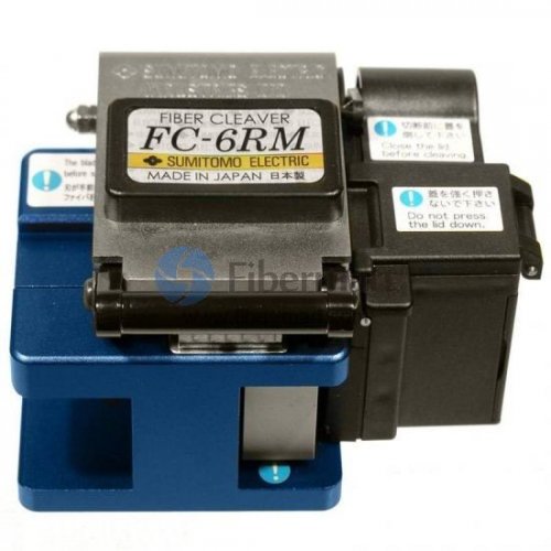
Precision Cleavers

Precision cleavers are the most commonly used cleavers in the industry. They use a diamond or tungsten wheel/blade to provide the nick in the fiber. Tension is then applied to the fiber to create the cleaved end face. The advantage of these cleavers is that they can produce repeatable results through thousands of cleaves by simply rotating the wheel/blade accordingly. Although more costly than scribe cleavers, precision cleavers can cut multiple fibers at one time with increased speed, efficiency, and accuracy. While in the past, scribe cleavers were widely used for fiber cleaving, precision cleavers are now developed to support various applications and multiple fiber cleaving. Precision cleavers contribute to better cleave, which ensures low splice loss and precision cleavers, besides, its blades have a much longer life span.

Operation method

1.Verify that the device has the blade sliding plate in front of one end, open the size platen;

2.Stripped fiber coating stripping fiber clamp reserve bare fiber length of 30-40mm, to wrap fiber, cotton wool or tissue dipped in alcohol then clean fiber. Rub with cotton wool or tissue paper, do not use the same cotton wool or tissue paper to rub the second (Note: Please use plain Greater than 99% alcohol).

3.Visual edge alignment of the fiber coating cutter ruler (12-20cm) appropriate scale, the left hand placed in the optical fiber oriented pressure tank the bare fiber placed straight on the left and right rubber mat.

4.Together on a small plate, large platen to promote devices blade slider the blade dicing fiber under surface, and is free to slide to the other side, cut fiber;

5.The left hand held onto the cutter, the right hand to open a large pressure plate and remove fiber debris into fixed container.

6.Pinch the optical fiber with the left hand while the right hand to open the small pressure plate, carefully remove the fiber cut end face, attention: the neat fiber cross-section do not touch it matter.

The advantages of fiber optic cleaver

1.Excellent beam quality of a smaller of focal diameter and high working efficiency, high quality;

2.High cutting speed: cutting speed greater than 10m/min;

3.Stable operation: the world’s top import fiber optic lasers, stable performance, key parts can reach 100,000 hours;

4.The high efficiency of photoelectric conversion: Compare with CO2 laser cutting machine, fiber optic laser cutting machine have three times photoelectric conversion efficiency;

5.Low cost: to save energy and protect the environment Photoelectric conversion rate as high as 25-30%. The low power consumption, which is the traditional CO2 laser cutting machine is only about 20% -30%;

6.Low maintenance costs: fiber line transmission, no need reflect lens, save maintenance costs;

7.Simple operation: optical fiber transmission lines, there is no adjustment of the optical path;

8.Super flexible optical effects: compact design, compact and easy to flexible manufacturing requirements.

Tips on Choosing Fiber Cleavers

1. Select fiber cleavers according to your application requirements. Fiber cleavers, designed for fusion splicing, need a low average angle that is one degree or less, whereas cleavers appropriate for mechanical connectors require angles below three degrees. So determine whether you require a single-fiber or multi-fiber cleaver before you cleave the fibers at one time.

2.Think twice before purchasing a cleaver built into a splicer. If you intend to purchase the built-in cleavers, you must check whether the cleaver or splicer requires maintenance. It may cause inconvenience to technician if they loses valuable tools, which can hold up the job at hand.

3.Purchase a cleaver with the latest automation features that can save a lot of labour and time. Fiber cleavers are always continuing to evolve with new and improved features, such as automated fiber scrap collection, automated scoring mechanisms, and the latest automatic blade rotation technology.

Conclusion

Precise cleaving is the premise of successful fusion splicing. Thus the quality of the fiber cleavers directly determines the quality of fiber optic splices or terminations. If the fiber ends were not cleaved perfectly, fiber loss would occur which would in turn affect the transmission of signals. To buy reliable and high precision fiber cleavers, please visit Fiber-Mart or contact us via product@fiber-mart.com.

 Fiber Optic Power Meter

Important specifications for fiber optic power meters include wavelength range, optical power range, power resolution and power accuracy. Some devices are rack-mounted or handheld. Today we will focus on fiber optic power meters.

Important specifications for fiber optic power meters include wavelength range, optical power range, power resolution and power accuracy. Some devices are rack-mounted or handheld. Today we will focus on fiber optic power meters.


What does Optical Power Meter (OPM)mean?

An optical power meter (OPM) is a device used measure the power in an optical signal. The term usually refers to a device for testing average power in fiber optic systems. Other general purpose light power measuring devices are usually called radiometers, photometers, laser power meters (can be photodiode sensors or thermopile laser sensors), light meters or lux meters.

An optical power meter (OPM) is a testing instrument used to accurately measure the power of fiber optic equipment or the power of an optical signal passed through the fiber cable. It also helps in determining the power loss incurred to the optical signal while passing through the optical media. An optical power meter is made up of a calibrated sensor that measures amplifier circuit and a display. The sensor normally consists of a silicon (Si), germanium (Ge) or indium gallium arsenide (InGaAs) based semiconductor. The display unit shows the measured optical power and the corresponding wavelength of the optical signal.


Explains Optical Power Meter (OPM)


OPM calibrates the wavelength and measures the power of an optical signal. Before testing, the required wavelength is set manually or automatically. Accurate calibration of the signal wavelength is necessary for accurate measurement of power level, otherwise the test may yield false reading.

Different sensor types used in OPMs have different characteristics. For example, Si sensors tend to become saturated at low power levels and can only be used in 850 nanometer bands, while Ge sensors saturate at high power levels, but perform poorly at low power.

To calculate the power loss, OPM is first connected directly to an optical transmission device through a fiber pigtail, and the signal power is measured. Then the measurements are taken through OPM at the remote end of the fiber cable. The difference between the two measurements displays the total optical loss the signal incurred while propagating through the cable. Adding up all the losses calculated at different sections yields the overall loss incurred to the signal.


Three types of equipment can be used to measure optical power loss:


  • Component equipment – Optical Power Meters (OPMs) and Stabilized Light Sources (SLSs) are packaged separately, but when used together they can provide a measurement of end-to-end optical attenuation over an optical path. Such component equipment can also be used for other measurements.
  • Integrated test set – When an SLS and OPM are packaged in one unit, it is called an integrated test set. Traditionally, an integrated test set is usually called an OLTS. GR-198, Generic Requirements for Hand-Held Stabilized Light Sources, Optical Power Meters, Reflectance Meters, and Optical Loss Test Sets, discusses OLTS equipment in depth.
  • An Optical Time Domain Reflectometer (OTDR) can be used to measure optical link loss if its markers are set at the terminus points for which the fiber loss is desired. However a single-direction measurement may not be accurate if there are multiple fibers in a link, since the back-scatter coefficient is variable between fibers. The accuracy of such a measurement can be increased if the measurement is made as a bidirectional average of the fiber. GR-196, Generic Requirements for Optical Time Domain Reflectometer (OTDR) Type Equipment, discusses OTDR equipment in depth.

c0f00911fe811834774c3adbdd42a464.image.500x500.jpg

Key Features

It can experiment at Voice, data and video signal synchronous measurement and display on BPON/EPON/GPON.
Providing simultaneous measurement for all three wavelengths on the fiber (1490nm, 1550nm,1310nm )
Used in Burst mode measurement of 1310nm upstream.
Use the software connect with PC, setting the threshold, data transfer, and calibration the wavelength.
USB communication port enables data transfer to a PC.1000measurement items can be saved in 3213 PON power meter or computer for data review.
With optical power meter modual, include 850、1300、1310、1490、1550、1625sixs( 3213AP,3213A  without  850nm wavelength);With visual fault locator modual(3213and3213AV)Optical power meter and VFL with one port.(only 3213A)
Optional Chinese/English display.
Offers up to 10 different threshold sets in total,Three status LEDs represent different optical signal conditions of Pass, Warn and Fail respectively.
10 minutes Auto-off function can be activated or deactivated
Good key design,high sensitivity, greatly reducing the volume and weight of the tester.
Different models corresponding to different function, according to own use to choose .


Summary


When you install and terminate fiber optic cables, you always have to test them. A test should be conducted for each fiber optic cable plant for three main areas: continuity, loss, and power. Fiber-Mart offers a full range of optical power meters to support FTTx deployments, fiber network testing, certification reporting capabilities and basic power measurements. Welcome to visit www.fiber-mart.com or Contact me at service@fiber-mart.com. 


Fbt Coupler Fiber Optic Patch Cables And Dwdm Sfp Transceiver

by http://www.fiber-mart.com

Fiber optic splitter is used to split the fiber optic light into several parts at a certain ratio. We use fiber optic splitter to distribute or combine optical signals in many applications, such as FTTH solution, etc. Fiber optic splitters are important passive components used in FTTX networks. Fiber optic splitters can be terminated with different kinds of connectors, the main package could be box type or stainless tube type, one is usually used with 2mm or 3mm outer diameter cable, the other is usually used with 0.9mm outer diameter cables.
Two kinds of fiber splitters are popular used, one is the traditional fused type fiber optic splitter (FBT coupler), which features competitive prices; the other is PLC fiber optic splitter, which is compact size and suit for density applications. Both of them have its advantages to suit for different requirement. FBT Couplers are designed for power splitting and tapping telecommunication equipment, CATV networks, and test equipment. These components are available individually or integrated into modules for fiber protection switching, MUX/DMUX, optical channel monitoring, and add/drop multiplexing applications.
Major differences between PLC splitters and FBT Coupler
1. Technology behind FBT Coupler and PLC splitter.
FBT coupler: Fused Biconical Taper, this is traditional technology to weld several fiber together from side of the fiber.
PLC splitter: Planar Lightwave Circuit is a micro-optical components product, the use of lithography, the semiconductor substrate in the medium or the formation of optical waveguide, to achieve
branch distribution function.
2. Disadvantages and advantages between FBT and PLC.
PLC splitter FBT coupler
SpliSplit Ratio (Max) 1*64 splits 1*4 splits
EveEveness Can split light evenly Eveness is not very precise
SizeSizeSize Compact size Big size for multi splits
Fiber Patch Cable also known as fiber jumper or fiber patch cord, which is a fiber optic cable terminated with fiber optic connectors on both ends. There are two major application areas of Fiber
Patch Cable: computer work station to outlet and fiber optic patch panels or optical cross connect distribution center. Fiber optic patch cables are for indoor applications only. Single-mode fiber
Patch cable is primarily used for applications involving extensive distances. Multimode fiber optic patch cord, however, is the cable of choice for most common local fiber systems as the devices for multimode are far cheaper.
Jfiberoptic Dense Wavelength Division Multiplexing (DWDM) Small Form-Factor Pluggable (SFP) is available in all 100 GHz C-band wavelengths on the DWDM ITU grid. They are designed to Multi-Source Agreement (MSA) standards to ensure broad network equipment compatibility. As multirate interfaces they support any protocol from 100 Mbps to 4.25 Gbps. DWDM SFP transceivers provide the high speeds and physical compactness that today’s networks require while delivering the deployment flexibility and inventory control that network administrators demand. The 1.25G DWDM SFP transceivers are small form factor pluggable modules for bi-directional serial optical data communications such as 4x/2x/1x Fibre Channel, SDH/SONET, Ethernet applications. We supply 1.25G DWDM SFP modules are hot pluggable and digital diagnostic functions area vailable via an I2C serial bus specified in the SFP MSA SFF-8472. The DWDM SFP transceiver has undergone rigorous qualification and certification testing to provide End-to-End Compatibility using switching equipment from CISCO, BROCADE, JUNIPER, ALCATEL, HP (select models), NORTEL, EMC, QLOGIC and other OEMs.

What are Fiber Optic Patch Cables

by http://www.fiber-mart.com

Fiber optic patch cable, often called fiber optic patch cord or fiber jumper cable, is a fiber optic cable terminated with fiber optic connectors on both ends. It has two major application areas: computer work station to outlet and fiber optic patch panels or optical cross connect distribution center. Fiber optic patch cables are for indoor applications only.
Fiber optic patch cables can be divided into different types based on fiber cable mode, cable structure, connector types, connector polishing types and cable sizes.
Fiber optic patch Cable Mode:
1. Single mode fiber patch cables:  Single mode fiber optic patch cables use 9/125 micron bulk single mode fiber cable and single mode fiber optic connectors at both ends. Single mode fiber optic cable jacket color is usually yellow. Here is the explanation of what is single mode and single mode fiber.
2. Multimode fiber patch cables: Multimode fiber optic patch cables use 62.5/125 micron or 50/125 micron bulk multimode fiber cable and terminated with multimode fiber optic connectors at both ends.  Multimode fiber optic cable jacket color is usually orange. Here is the explanation of what is multimode and multimode fiber.
3. 10gig multimode fiber optic patch cables:  10Gig multimode fibers are specially designed 50/125 micron fiber optimized for 850nm VCSEL laser based 10Gig Ethernet. They are backward compatible with existing network equipment and provide close to three times the bandwidth of traditional 62.5/125 multimode fibers. 10 Gigabit is rated for distances up to 300 meters using 850nm Vertical Cavity Surface Emitting Lasers (VCSEL). 10Gig fiber optic cable jacket is usually aqua.
Fiber patch Cable Structure:
1. Simplex fiber optic patch cables: Simplex fiber patch cable has one fiber and one connector on each end.
2. Duplex fiber optic patch cables: Duplex fiber patch cable has two fibers and two connectors on each end. Each fiber is marked “A” or “B” or different colored connector boots are used to mark polarity.
3. Ribbon fan-out cable assembly: For ribbon fan-out cable assembly, one end is ribbon fiber with multi fibers and one ribbon fiber connector such as MTP connector (12 fibers), the other end is multi simplex fiber cables with connectors such as ST, SC, LC, etc.