Introduction of Fiber Optic Cleaving

As we know, in most cases, when a fiber is used or spliced, it is essential to prepare clean ends. Stripping, cleaving, polishing are the basic steps to ensure fiber ends clean and smooth. Cleaving, an essential step of making fiber ends clean, though it’s a simple mean, but it works surprisingly well, at least for standard glass fibers. Thus, I want to share something about the cleaving in this paper today.

As we know, in most cases, when a fiber is used or spliced, it is essential to prepare clean ends. Stripping, cleaving, polishing are the basic steps to ensure fiber ends clean and smooth. Cleaving, an essential step of making fiber ends clean, though it’s a simple mean, but it works surprisingly well, at least for standard glass fibers. Thus, I want to share something about the cleaving in this paper today.

图片1

Basics of Fiber Optic Cleaving

Fiber optic cleaving is one of the several processes in the preparation for a fiber splice operation. The purpose of cleaving is to prepare the end of the fiber so that it makes a very nearly perfect right angle with the body of the fiber and that this end face is nearly perfectly smooth. With a well-performed cleaving operation, a clean and flat endface was created perpendicular to the length of the fiber, with no protruding glass on either end. Besides it can also help to achieve a successful low loss splice of an optical fiber.


The technique of Fiber Optic Cleaving

A general strategy involved in the technique of fiber optic cleaving is known as the scribe-and-tension or scribe-and-break strategy. With the use of cutting tool made from materials such as diamond, sapphire or tungsten carbide, this process involves the introduction of a crack in the fiber, then followed by the application of tensile stress in the vicinity of the crack.

However, the specific implementations of the cleaving can be various thus lead to cleaves of different qualities. Some implementations may apply the tensile force uniformly across the cross section of the fiber while others might bend the fiber around a curved surface, causing excessive tensile stress on the outside of the bend. Besides, the crack in the fiber may also be generated in different ways: the crack may be introduced at a single point on the circumference or it may be generated all along the circumference of the fiber prior to the application of the tensile force. The circumferential introduction of the crack often allows fibers of considerably large diameters to be cleaved while maintaining high quality of the cleave.

图片2

Two Types of Fiber Optic Cleavers

As mentioned before, fiber optic cleavers can be classified into precision cleavers and cheap or scribe cleavers.

Scribe Cleavers—The scribe or manual cleaver, which is cheaper than the precision cleaver, is the most original type of fiber optic cleaver. Scribe cleavers are usually shaped like ballpoint pens with diamond tipped wedges or come in the form of tile squares. The scribe has a hard and sharp tip, generally made of carbide or diamond, to scratch the fiber manually. Then the operator pulls the fiber to break it. Since the breaking process is under manual control, it is hard to control the force, which makes the cleaving less accurate and precise. That’s why most technicians shy away from these cheap cleavers.

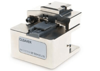
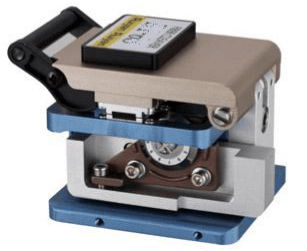
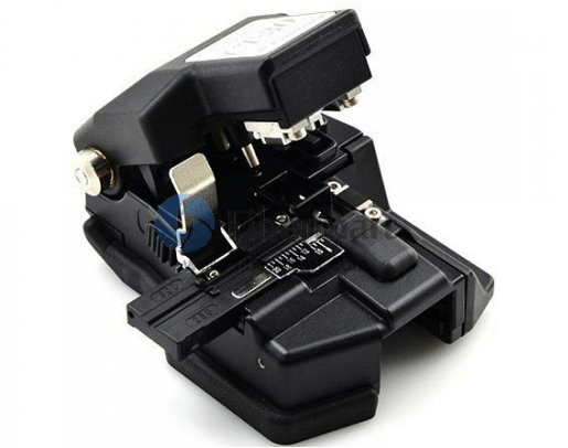
Precision Cleavers—As the name implies, precision cleavers can do a preciser cleaving job compared to the scribe cleavers. A precision cleaver uses a diamond or tungsten wheel/blade to provide the nick in the fiber. Tension is then applied to the fiber to create the cleaved end face. The advantage of the precision cleavers is that they can produce repeatable results through thousands of cleaves by simply just rotating the wheel/blade accordingly. Although they are more costly than scribe cleavers, precision cleavers can cut multiple fibers with increasing speed, efficiency, and accuracy. As the fusion splicers became popular, precision cleavers were developed to support various splicing works. Precision cleavers are deal for fusion splicing standard 125/250um & 125/900um fibers and preparing fiber for various pre-polished connectors.

3

Operation Procedure for Fiber Cleavers

A fiber cleaver utilizes an automatic anvil drop for fewer required steps and better cleaving consistency. The automated anvil design can save time and significantly improve the quality of the cleave by eliminating human error and subpar cleaves associated with scribes and manual cleavers. To perfectly cleave optical fibers, perform the following steps:

Step 1: Open the body cover and put the stripped fiber on the v-groove.

Step 2: Close the holder cover.

Step 3: Close the cover and move the slider forward to cleave the fiber.

Step 4: Open the cover and check the cleaved fiber.

Step 5: Open the holder cover and take out the cleaved fiber.

Step 6: Remove the chip of cleaved fiber with a pair of tweezers.

6

Tips on Choosing Fiber Cleavers

1.Select fiber cleavers according to your application requirements. Fiber cleavers, designed for fusion splicing, need a low average angle that is one degree or less, whereas cleavers appropriate for mechanical connectors require angles below three degrees. So determine whether you require a single-fiber or multi-fiber cleaver before you cleave the fibers at one time.

2.Think twice before purchasing a cleaver built into a splicer. If you intend to purchase the built-in cleavers, you must check whether the cleaver or splicer requires maintenance. It may cause inconvenience to technician if they loses valuable tools, which can hold up the job at hand.

3.Purchase a cleaver with the latest automation features that can save a lot of labour and time. Fiber cleavers are always continuing to evolve with new and improved features, such as automated fiber scrap collection, automated scoring mechanisms, and the latest automatic blade rotation technology.


Conclusion

To get good fiber optic splices or terminations, especially when using the pre-polished connectors with internal splices, it is extremely important to cleave the fiber properly. As we know, fiber splicing requires mating two fiber ends. Any defect of the ends would impact the performance of fiber splicing.To buy reliable and high precision fiber cleavers, please visit www.fiber-mart.com or contact us product@fiber-mart.com.


Introduction of Loopback Cable and How do we Create it?

A loopback cable is also known as loopback plug or loopback adapter, which is a plug used to test physical ports to identify network issue. It provides system test engineers a simple but effective way of testing the transmission capability and receiver sensitivity of network equipment.

In our day to day jobs we find ourselves lugging around more and more hardware; pda, laptop, cell phone, and sometimes even hubs. Why do we carry a hub around when sometimes all we need is a link on our ethernet cards so that all the applications on the system work. Yes, I know you could setup a loopback software adapter. But if you are looking to have the system configured as close to the real setup as possible and you don’t want to carry a hub around, just to get a link light on your NIC. Consider building yourself a loopback cable.

rt

What Is Loopback Cable?

A loopback cable is also known as loopback plug or loopback adapter, which is a plug used to test physical ports to identify network issue. It provides system test engineers a simple but effective way of testing the transmission capability and receiver sensitivity of network equipment. In a word, it is a connection device that is plugged into a port to perform a loopback test. There are loopback plugs for many different ports, including serial ports, Ethernet ports, and WAN connections.

Fiber-Loopback-2

Loopback Cable Type

Fiber Loopback Cable

Fiber optic loopback incorprates two fiber optic connectors which are plugged into the output and input port of the equipment respectively. Therefore, fiber loopback cables can be classified by the connector types, such as LC, SC, FC, MTRJ. These fiber optic loopback plug connectors are compliant to IEC, TIA/EIA, NTT and JIS specifications. Besides, fiber optic loopback cables also can be divided into single mode and multimode fiber loopback. To describe this item clearly, I will take LC fiber optic loopback cable as an example, which is one of the most popular cables (as shown in the following figure). The LC fiber optic loopback cables support the test of transceivers featuring LC interface. They can comply with the RJ-45 style interface with low insertion loss, low back reflection and high precision alignment. LC loopback cables can be 9/125 single mode, 50/125 multimode or 62.5/125 multimode fiber type.

ytr

RJ45 Loopback Cable

A Gigabit RJ45 loopback cable is an exceedingly user friendly cable tester. It looks like a simple plug at first glance, but the compact and rugged design makes it highly portable and usable in the tightest corners. All you have to do is to simply plug the Gigabit RJ45 loopback into the jack that you want to test or the one you are suspicious about. If the link LED on your switch is active, it means that the connection is operating perfectly. The RJ45 loopback cable will negate the necessity to carry a bulky network hub around.

sc

How to build the loopback cable simplified?

If you are handy with building ethernet cables, the simple explanation is;

  1. Redirect Pin 1 to Pin 3 and Pin 2 to Pin 6.
  2. Make sure you create tight twists to account for signal interference at such a short length.

4

How to build a loopback cable illustrated?

Step 1. Get a pair of approximately 4 inches in length of cat 5 cable.

Step 2. Leave approximately 1/2 inch at end and start twisting, very tightly.

Note: If your fingers start to hurt, you may want to use a tool to help with the twisting. Notice how tightly wound the cable is. If the twists are not close enough the loopback will not work. Please twist to match picture.

Step 3. After twisting is done, fold cable and line up the ends. Cut if you must to line up cables. Line up the cables so that the cables are in the proper alignment to prepare for insertion into RJ-45 end.

 Step 4: Insert cable into RJ-45 end. (do not crimp yet.) Remember, 1236 pins.

Step 5. Insert plastic tubing over the wire and into the RJ-45 end. Now crimp the end with a crimping tool.

Note: When you first plug in the loopback cable, wait approximately 10 seconds to get a link light. No more carrying around a hub just to get a link light.

5

Conclusion

All in all, If we know what a is loopback cables and know how to create loopback cables, it will bring many benefits to our work and life.loopback cables play an important role in troubleshooting in laboratories and manufacturing environments. They facilitate the testing of simple networking issues and are available at very low costs. There are many loopback cable manufactures on the market, providing single mode and multimode fiber optic loopback plugs available with FC, LC, MT-RJ, SC connectors. Fiber-Mart is one of the fiber loopback cable providers, all loopback cables are precision terminated and feature extremely low loss characteristics for transparent operation in the test environment.

Singlemode fiber and multimode fiber different and selection method(2)

The application of fiber optics is being gradually extended from the trunk or the computer room to the desktop and residential users, which means that more and more users who do not understand the characteristics of the fiber have come into contact with the fiber optic system. Therefore, when designing fiber link systems and selecting products, full consideration should be given to the current and future application requirements of the system, use of compatible systems and products, the greatest possible ease of maintenance and management, and adaptation to the ever-changing field conditions and user installation requirements.

yt

1. Can a fiber optic connector be terminated directly on a 250 μm fiber?  


Loose sleeve fiber optic cable contains bare fiber with an outer diameter of 250 μm, which is very small and fragile. It is unable to fix the fiber and is not enough to support the weight of the fiber optic connector and is very insecure. The connector is terminated directly on the fiber optic cable. At a minimum, a 900 μm tight jacket is required to wrap around the 250 μm fiber to protect the fiber and support the connector.

2. Can the FC connector be connected directly to the SC connector?

Yes, this is just a different connection method for two different types of connectors.
If you need to connect them, you must select a mixed adapter and use the FC/SC adapter to connect the FC connector and the SC connector at both ends. This method requires that the connectors should all be flat ground. If you absolutely need to connect APC connectors, you must use a second method to prevent damage.

The second method is to use a hybrid jumper and two connection adapters. Hybrid patch cords use different types of fiber connectors at both ends. These connectors will connect to the place where you need to connect. In this way, you can use a universal adapter to connect the system in the patch panel, but bring the system budget to budget. The increase in the number of connector pairs.

3. The fixed connection of optical fibers includes mechanical optical fiber connection and thermal welding. What are the selection principles for mechanical optical fiber connection and thermal welding?

Mechanical fiber optic connection, commonly known as fiber optic cold connection, refers to an optical fiber connection method in which a single or multi-fiber optical fiber is permanently connected through a simple connection tool and a mechanical connection technology without the need of a thermal fusion bonding machine. In general, mechanical splices should be used in place of thermal fusion when splices are made at a small number of cores dispersed at multiple locations.

yty
Mechanical fiber optic connection technology is often used in engineering practices such as line repairs and small-scale applications in special occasions. In recent years, with the large-scale deployment of fiber-to-the-desktop and fiber-to-the-home (FTTH), it has been recognized that mechanical fiber optic connection is an important means of fiber optic connection.

For fiber-to-the-desktop and fiber-to-the-home applications with a large number of users and geographically dispersed features, when the scale of the users reaches a certain level, the construction complexity and construction personnel and fusion splicer cannot meet the time requirements for users to open services. Because of the simple operation, short training cycle, and low equipment investment, the mechanical fiber connection method provides the most cost-effective solution for optical fiber connection for large-scale deployment of optical fibers. For example, in the high corridors, narrow spaces, insufficient lighting, inconvenient on-site power and other occasions, mechanical fiber optic connection provides a convenient, practical, fast and high-performance optical fiber continuation means for design, construction and maintenance personnel.

ytyy

 4. What is the difference between fiber optic splice enclosure requirements and fiber optic splice closures used in telecom operators’ outdoor lines in fiber-to-the-home systems?

First of all, in the fiber-to-the-home system, it is necessary to reserve the position of the optical splitter installation and termination, accommodation, and protection of the jumper to and from the optical splitter in the joint box according to actual needs. Because the actual situation is that the optical splitter may be located in the cable joint box, optical cable transfer box, wiring box, ODF and other facilities, and in which the optical cable termination and distribution.

Secondly, for residential quarters, the optical fiber cable splice box is installed in a buried manner. Therefore, the optical cable splice box has higher requirements for buried performance.

In addition, in the fiber-to-the-home project, it may be necessary to consider the entry and exit of a large number of small-core optical cables.

Singlemode fiber and multimode fiber different and selection method(1)

1.What is singlemode and multimode fiber? What is the difference between them?

The concept of single-mode and multi-mode is to classify fibers according to the propagation mode—the concept of multi-mode fiber and single-mode fiber propagation mode. We know that light is an extremely high-frequency (3×10¹⁴Hz) electromagnetic wave. When it propagates in an optical fiber, it is found from theories of wave optics, electromagnetic fields, and Maxwell equations.

When the fiber core has a geometric dimension much larger than the wavelength of the light, the light will propagate in the fiber in dozens or even hundreds of propagation modes, such as TMmn mode, TEmn mode, HEmn mode, etc. (where m, n=0, 1, 2, 3, …).

Among them, the HE11 mode is called the basic mode, and the rest are all called high-order modes.

Multimode fiber

When the fiber’s geometric size (mainly the core diameter d1) is far greater than the wavelength of light (about 1μm), there will be dozens or even hundreds of propagation modes in the fiber. Different propagation modes have different propagation speeds and phases, resulting in delays and widening light pulses after long-distance transmission. This phenomenon is called the modal dispersion of the fiber (also called inter-modal dispersion).

Mode dispersion can narrow the bandwidth of multimode fiber and reduce its transmission capacity. Therefore, multimode fiber is only suitable for smaller-capacity fiber communication.

The refractive index distribution of a multimode fiber is mostly a parabolic distribution, ie, a graded index profile. Its core diameter is about 50μm.

图片1

Single Mode Fiber

When the fiber’s geometry (mainly the core diameter) can be similar to the wavelength of light, if the core diameter d1 is in the range of 5~10μm, the fiber only allows one mode (base mode HE11) to propagate in it, and all other high-order modes are all cut off. This kind of fiber is called single-mode fiber.
Since it only has one mode to propagate and avoids the problem of mode dispersion, single-mode fiber has a very wide bandwidth and is particularly suitable for large-capacity optical fiber communications. Therefore, in order to achieve single-mode transmission, the parameters of the fiber must satisfy certain conditions. Through formulae calculations, for a fiber with NA=0.12, single-mode transmission above λ=1.3 μm, the radius of the fiber core should be ≤ 4.2 μm, ie its core diameter d1 ≤ 8.4 μm.
Because the core diameter of a singlemode fiber is very small, more stringent requirements are imposed on its manufacturing process.

2.What are the advantages of using optical fiber?

1) The passband of the fiber is very wide and the theory can reach 30T.
2) The length of non-relay support is up to tens to hundreds of kilometers, and the copper wire is only a few hundred meters.
3) Not affected by electromagnetic fields and electromagnetic radiation.
4) Light weight and small size.
5) Optical fiber communication is not powered, and the use of safety can be used in flammable, volatile and other places.
6) The use of a wide range of ambient temperatures.
7) Long service life.

图片2

3.how to choose the optical cable?

In addition to selecting the number of optical fiber cores and optical fibers, the optical cable must be selected according to the use environment of the optical cable to select the structure of the optical cable and the outer sheath.

1) Optical cable for outdoor use When loosely buried, it is better to use loose-sheathed cable. When overhead, a loose PE cable with a black PE sheath with two or more ribs can be used.
2) Optical fiber cables used in buildings should use tight-fitting optical cables and pay attention to their fire-retardant, toxic and smoke characteristics. The type of flame-retardant but smoke (Plenum) or flammable and non-toxic type (LSZH) can be used in the pipeline or in forced ventilation. The type of flame-retardant, non-toxic and non-smoking (Riser) should be used in the exposed environment.
3) When vertical or horizontal cabling is installed in a building, it can be used when using tight-fit optical cable, distribution optical cable or branch optical cable that are common in the building.
4) Select single-mode and multi-mode optical cables based on network applications and optical cable application parameters. Usually, indoor and short-distance applications use multimode optical cables, while outdoor and long-distance applications use single-mode optical cables.

4.In the connection of optical fibers, how to choose different applications of fixed connection and active connection?

The active connection of the fiber is achieved through a fiber optic connector. An active connection point in the optical link is a clear split interface. In the choice of active connection and fixed connection, the advantages of fixed connection are reflected in lower cost, light loss, but less flexibility, and the active connection is the opposite. When designing the network, it is necessary to flexibly select the use of activities and fixed connections according to the entire link situation to ensure flexibility and stability, so as to give full play to their respective advantages. The active connection interface is an important test, maintenance, and change interface. The active connection is relatively easy to find the fault point in the link than the fixed connection, which increases the convenience of replacement of the faulty device, thereby improving system maintenance and reducing maintenance costs.

图片3

5.Fibers are getting closer to user terminals. What do you need to pay attention to when it comes to the meaning of “fiber to the desktop” and system design?

“Fiber-to-the-desktop” in the application of the horizontal subsystem, and the relationship between copper and copper cable is complementary and indispensable. Optical fiber has its unique advantages, such as long transmission distance, stable transmission, free from electromagnetic interference, high support bandwidth, and no electromagnetic leakage. These characteristics make the optical fiber play an irreplaceable role in some specific environments:
1) If the information point transmission distance is greater than 100m, if you choose to use copper cable. Replicators must be added or network equipment and weak rooms must be added to increase costs and hidden troubles. Using fiber can easily solve this problem.
2) There are a large number of sources of electromagnetic interference in specific work environments (such as factories, hospitals, air-conditioning rooms, power equipment rooms, etc.), and optical fibers can be operated stably without electromagnetic interference in these environments.
3) There is no electromagnetic leakage in the fiber. It is very difficult to detect the signal transmitted in the fiber. It is a good choice for places where the security level is relatively high (such as military, R&D, auditing, government, etc.).
4) The environment with high demand for bandwidth has reached more than 1G. Optical fiber is a good choice.

There are many differences between single-mode fiber and multi-mode fiber, and the selection method is not the same. Let’s talk about it today. For more details, please keep an eye on Singlemode fiber and multimode fiber different and selection method(2).

8000 meters deep submarine actually there are optical cables? Is the person who spreads the cable is Iron Man?

If you compare the earth to a computer motherboard. From the phone poles with cables to the warning signs that lay the optical fibers, the world we live in is surrounded by countless lines. In fact, the Internet infrastructure that we can see with our naked eyes is only the tip of the iceberg, and there are countless cables laid in the depths of the dark ocean.You must be more interested in what you would like to eat than you would like to eat at dinner.

1.On the surface of the sea, the ship releases the cable.

图片1
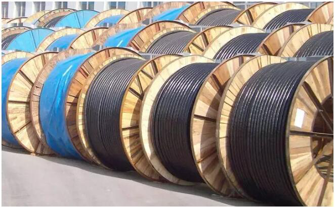
2.Under the sea, cable ploughs fix the cable to the bottom of the sea. There is also a repeater every 40km to 60km.

图片23.Guaranteed signal.How many optical cables do you need to bring?

图片3

Did you see the turntable on the boat?  It can be said to be super long

图片4
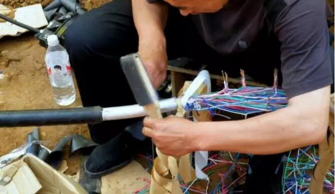
The process looks simple, Someone has to ask, is the pressure on the bottom of a few kilometers so large that the fiber is not easily damaged?

Responsibly tell you that submarine cables are more fragile than underground cables, and that different depths of maintenance are different:

1.The general cable fault location receives and sends a complete set of signals first, because the damage of the optical cable is usually the internal fiber breakage, the breakage location will reflect the signal, and the recovered reflection signal is compared with the shape and time of the signal calculated by the mathematical algorithm. Locate the specific location of the fiber breakage.

2.The cable repair ship went to the accident site to repair it. If the water depth is within two kilometers, an underwater robot is generally used to guide to the fault location through an artificial signal, and the damaged optical cable is cut off, and the remaining two ends are pulled back to the repair ship for repair.

3.If the water depth exceeds 2,000 meters, due to pressure problems, deep water grabs will be used, and the image is a hook. If it is a sandy seabed, the optical cable will be directly returned to the sea surface. If it is a rocky seabed, the grab must be along a certain length of the optical cable, so that the position of the optical cable can be adjusted more easily to prevent it from being pinched by rocks.图片5

4.If the water depth is too deep, a single grab cannot pull the entire cable directly back to the surface. At this point, the fiber optic cable needs to be cut off, and now a head A1 is brought back to be fixed with a buoy, and then the other head A2 is pulled with another grab.

5.Fiber optic cable repair is mainly the work of fiber-optic welding. A2 is welded to the newly added spare cable B. Then the repair boat is close to the buoy, and the A1 is rejoined to the remaining part of B. The repaired cable is longer than the original one. The new cable is U-shaped on the sea floor. After the welding is completed, wait until the communication test is successful before returning the cable.

Therefore, the cost of submarine cable is quite high. The cost of a transoceanic fiber cable is several hundred million US dollars. Coupled with the monopoly of real estate giants, the monopoly access prices of domestic operators, the terrible reasons for the high cost of broadband in Hong Kong have also been explained.

Introduction of SM to MM Media Converters

What is SM to MM Media Converter?

Enterprise networks often require conversion from MM to SM fiber, which supports longer distances than MM fiber. Mode conversion is typically required when lower cost legacy equipment uses MM ports but connectivity is required to SM equipment, a building has MM equipment, while the connection to the service provider is SM, and MM equipment is in a campus building but SM fiber is used between buildings.

SM to MM Media Converters are Fiber-to-Fiber Media Converters used to conduct the transparent conversion between singlemode and multimode fiber for applications where media conversion required between multimode segments separated by long distances. Fiber-Mart provides various type of singlemode to multimode media converters, which fulfill the conversion at 850/1310nm or 850/1310/1550nm wavelengths and transmission distance up to 120 km. In addition, these Fiber-to-Fiber media converters also support transmission between dual fiber and simplex fiber.

图片1

Why use SM to MM fiber converters?

From the aspect of photoelectric conversion, the use of fiber converters greatly reduces the cost of fiber-to-the-home. What effect does it have on the conversion between singlemode-multimode, simplex-duplex, and different wavelengths? The following examples will illustrate the important role of fiber converters in these applications.

As we all know, when the distance between two connection points in a network system is long, we need to use singlemode fiber optic cables to transmit optical signals to ensure the normal transmission of signals. Therefore, many network service providers use singlemode fiber optic cables for transmission. Optical signals, and many devices in data centers or enterprise networks are multimode fiber ports. At this time, a device is required to achieve single mode-multimode conversion of optical signals. Campus network is such a common application. The equipment in the campus building is usually a multimode fiber port, and the connection between buildings is usually a single mode fiber optic cable. The singlemode multimode conversion function of the fiber converter has been fully implemented at this time.

www.fibermart.com14

Select SM to MM fiber converter considerations?

Whether the serial fiber converter is easy to use, especially whether the networking is simple, needs to be examined from the following aspects:

1, single fiber, double fiber optional. Sometimes the optical fiber used in serial optical fiber networking is a certain optical fiber core that is distributed in the same optical cable that contains multi-core optical fibers. Obviously, using a single optical fiber core can save one optical fiber core compared to dual-core optical fibers.

2, volume and power consumption. In a complex optical fiber network, a large number of optical fiber converters are used. Therefore, the use of a small-sized optical fiber converter can greatly reduce the size of the cabinet, and a product with a low power consumption can reduce the size and cost of the power supply.

3, the versatility of the software. Is nothing to do with RS-232/RS-485 communication software, does not require settings, and is a true zero delay.

4, the versatility of single mode, multimode fiber. In many cases, serial optical fiber networking uses prefabricated fiber-optic cables, such as those used in Ethernet fiber-optic networks, and may be used for both long-distance single-mode fibers and near-distance multimode fibers.

eeee

Conclusion

Optical fiber converters are cost-effective solutions for expanding networks such as single-mode-multi-mode, simplex-duplex, and switching between different wavelengths, and increasing optical fiber capacity. They have wide applications in optical networks. Fiber-Mart provides various types of single mode to multimode media converters, which fulfill the conversion at 850/1310nm or 850/1310/1550nm wavelengths and transmission distance up to 120 km.