Some things you must know about Fusion Splicer

What is Fusion Splicer?

Fusion splicing is the act of joining two optical fibers end-to-end using heat. The goal is to fuse the two fibers together in such a way that light passing through the fibers is not scattered or reflected back by the splice, and so that the splice and the region surrounding it are almost as strong as the intact fiber.

What is Fusion Splicer?

Fusion splicing is the act of joining two optical fibers end-to-end using heat. The goal is to fuse the two fibers together in such a way that light passing through the fibers is not scattered or reflected back by the splice, and so that the splice and the region surrounding it are almost as strong as the intact fiber. The source of heat is usually an electric arc, but can also be a laser, or a gas flame, or a tungsten filament through which current is passed. and thus the splice as well as the region surrounding it are almost as strong because virgin fiber itself.

81cc

The basic fusion splicer apparatus includes two fixtures which the fibers are mounted and two electrodes. Inspection microscope assists in the placement in the prepared fiber ends into a fusion-splicing apparatus. The fibers they fit in to the apparatus, aligned, and then fused together.

Initially, fusion splicing used nichrome wire as the heating unit to melt or fuse fibers together. New fusion-splicing techniques have replaced the nichrome wire with fractional co2 lasers, electric arcs, or gas flames to heat the fiber ends, causing them to fuse together. The little size of the fusion splice along with the development of automated fusion-splicing machines make electric arc fusion the most popular splicing approaches to commercial applications.

81c

Fusion Splicing vs Mechanical Splicing

There are two types of optic fiber splicing. One is fusion splicing we mentioned above, another is mechanical splicing. In mechanical splicing two fiber optic cables are held end to end inside a sleeve using some mechanical mechanism. In this type of technique fibers aren’t joined permanently rather just accurately hold together, so that light can easily pass through from one end to another, while in fusion splicing two fibers are fused or wielded together using an electric arc, fusion splicing is most widely used technique because it provides a reliable join with lower insertions loss and practically no back reflection. Fusion splicing is generally applied on single mode fibers but in some special cases it can also be used for multi mode fibers.

The process of fusion splicing

The process of fusion splicing normally involves heat to melt or fuse the ends of two optical fibers together. The splicing process begins by preparing each fiber end for fusion.

121

1.Stripping the fiber

Stripping is the act of removing the protective polymer coating around optical fiber in preparation for fusion splicing. The splicing process begins by preparing both fiber ends for fusion, which requires that all protective coating is removed or stripped from the ends of each fiber.

2.Cleaning the fiber

The customary means to clean bare fibers is with alcohol and wipes. However, high purity isopropyl alcohol (IPA) is hygroscopic: it attracts moisture to itself. This is problematic as IPA is either procured in pre-saturated wiper format or in (host) containers ranging for USA quart to gallon to drums. From the host container the IPA is transferred to smaller more usable containers. The hydroscopic nature of IPA is such that the highest quality at 99.9% is also the most hygroscopic. This means that moisture absorption into both the host container as well as the actual user’s container begins with the time the original container is opened and continues as amounts are transferred and removed from both.

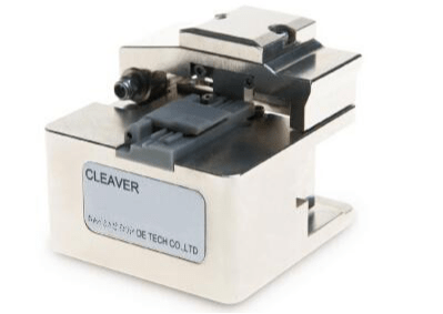
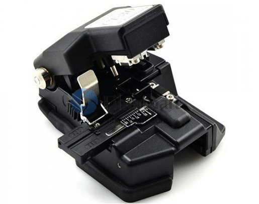
3.Cleaving the fiber

The fiber is then cleaved using the score-and-break method so that its end-face is perfectly flat and perpendicular to the axis of the fiber. The quality of each fiber end is inspected using a microscope. In fusion splicing, splice loss is a direct function of the angles and quality of the two fiber-end faces. The closer to 90 degrees the cleave angle is the lower optical loss the splice will yield. The quality of the cleave tool being used is critical.

6s

4.Splicing the fibers

Fiber spliced, still unprotected, Current fusion splicers are either core or cladding alignment. Using one of these methods the two cleaved fibers are automatically aligned by the fusion splicer[1] in the x,y,z plane, then are fused together. Prior to the removal of the spliced fiber from the fusion splicer, a proof-test is performed to ensure that the splice is strong enough to survive handling, packaging and extended use. The bare fiber area is protected either by recoating or with a splice protector. A splice protector is a heat shrinkable tube with a strength membrane and less loss.

5.Protecting the fiber

After the fibers have been successfully fused together, the bare fiber is protected either by re-applying a coating or by using a splice protector.

565

A simplified optical splicing procedure includes:

Characteristics of placement of the splicing

A simplified optical splicing procedure includes:

Characteristics of placement of the splicing process.

Checking fiber optic splice closure content and supplementary kits.

Cable installation in oval outlet.

Cable preparation.

Organization of the fibers inside the tray.

Installing the heat-shrinkable sleeve and testing it.

81

Conclusion

Fusion splicing provides permanent low-loss connections that are performed quickly and easily, which are definite advantages over competing technologies.When it comes to optical fiber fusion splicers, no other company in the world can match Fiber-MART for innovation, speed, and performance. The entire industry-leading range of splicers offers quick termination and new standards in heater shrink time. Fiber-Mart strives for even better standards each day. Like Sumitomo Type-81C Fusion Splicer, Innovation is key. It can revolutionized on-site connectivity, speed and brought lower project costs for the migration of the network. As the major leader in optical fiber and connectivity solutions, customers can expect reliability, flexibility and unbelievable performance. After all, network infrastructure expansion becomes easy when you use state-of-the-art fusion splicer solutions.Any question or need pls feel free to contact with us. E-mail: product@fiber-mart.com.


Introduction of Fiber Optic Pigtail

Fiber optic pigtail offers an optimal way to joint optical fiber, which is used in 99% of single-mode applications.

We know the way that cables are attached to the system is quite essential to the performance of the telecommunication network. Joining optical fibers with a fiber optic pigtail is proven and considered to be an effective way to ease fiber termination. As the cable is connected properly, it enables optical signals to pass with little return loss and low attenuation. Fiber optic pigtail offers an optimal way to joint optical fiber, which is used in 99% of single-mode applications.

etet

  1. What is Fiber Optic Pigtail ?

Fiber optic pigtail is a fiber cable end with fiber optic connectors at only either side of the cable while leaving sleep issues no connectors, so the connector side could be from the equipment and the other part can be melted with optical cable fibers.

Fiber optic pigtails are utilized to achieve accurate mounting for precision alignment of fiber optical components. They’re usually used with fiber optic management equipment like ODF, splice closures and cross cabinets.

tr

A fiber pigtail is really a single, short, usually unbuffered, optical fiber which has an optical connector pre-installed on one end along with a period of exposed fiber in the other end. The end of the pigtail is stripped and fusion spliced to a single fiber of a multi-fiber trunk. Splicing of pigtails to each fiber within the trunk “breaks out” the multi-fiber cable into its component fibers for connection to the end equipment.

Fiber pigtails can have female or male connectors. Female connectors might be mounted in a patch panel, often in pairs although single-fiber solutions exist, to allow them to be connected to endpoints or other fiber runs with patch fibers. Alternatively they can have male connectors and plug directly into an optical transceiver.

trt

2. Fiber Optic Pigtail Types

Fiber optic pigtails are available in various types: Grouped by pigtail connector type, there are LC fiber optic pigtails, SC fiber pigtails and ST fiber pigtails, etc. By fiber type, there are single-mode fiber optic pigtail and multimode fiber optic pigtail. And by fiber count, 6 fibers, 12 fibers optic pigtails can be found in the market.

  • By Fiber Type

Fiber optic pigtails can be divided into single-mode (colored yellow) and multimode (colored orange) fiber. Multimode fiber optic pigtails use 62.5/125 micron or 50/125 micron bulk multimode fiber cables and terminated them with multimode fiber optic connectors at one end. 10G multimode fiber cables (OM3 or OM4) are also available in fiber optic pigtails. The jacket color of 10G OM3 and OM4 fiber optic pigtail is usually aqua. Single-mode fiber pigtail cables use 9/125 micron single-mode fiber cable and terminated with single-mode fiber connectors at one end.

  • By Connector Type

According to different types of pigtail cable connector terminated at the end, there are LC fiber pigtail, SC fiber pigtail, ST fiber pigtail, FC fiber pigtail, MT-RJ fiber pigtail, E2000 fiber pigtail and so on. With different structures and appearance, each of them has their own advantages in different applications and systems. Let’s go through some widely used ones.

SC Fiber Optic Pigtail: SC pigtail cable connector is a non-optical disconnect connector with a 2.5mm pre-radiused zirconia or stainless alloy ferrule. SC fiber pigtail is economical for use in applications such as CATV, LAN, WAN, test and measurement.

FC Fiber Optic Pigtail: FC fiber pigtail takes the advantage of the metallic body of FC optical connectors, featuring the screw type structure and high precision ceramic ferrules. FC fiber optic pigtails and its related products are widely applied for the general applications.

ST Fiber Optic Pigtail: ST pigtail connector is the most popular connector for multimode fiber optic LAN applications. It has a long 2.5mm diameter ferrule made of ceramic (zirconia), stainless alloy or plastic. Hence SC fiber pigtails are commonly seen in telecommunications, industry, medical and sensor fields.

Like fiber optic patch cords, fiber optic pigtails can be divided into UPC and APC versions. Most commonly used types are SC/APC pigtail, FC/APC pigtail and MU/UPC pigtail.

  • By Application Environment

Some pigtail cables are specially installed to withstand the harsh or extreme environments, so here comes armored fiber pigtail and waterproof fiber pigtail.

Armored Pigtail: enclosed with stainless steel tube or other strong steel inside the outer jacket, armored fiber optic pigtails provide extra protection for the fiber inside and added reliability for the network, while reduce the unnecessary damage caused by rodents, construction work, weight of other cables.

Waterproof Pigtail: designed with a stainless steel strengthened waterproof unit and armored outdoor PE (Poly Ethylene) jacket, waterproof fiber pigtail is a great fit in harsh environments, like communication towers, CATV and military. Waterproof pigtail cable boosts good toughness, tensile and reliable performance, facilitating the use in outdoor connections.

  • By Fiber Count

Fiber optic pigtails could have 1, 2, 4, 6, 8, 12, 24 and 48 strand fiber counts. Simplex fiber optic pigtail has one fiber and a connector on one end. Duplex fiber optic pigtail has two fibers and two connectors on one end. Each fiber is marked “A” or “B” or different colored connector boots are used to mark polarity. Similarly, 4, 6, 8, 12, 24, 48 and more than 48 fibers fiber optic pigtails have their corresponding feature.

Note: Fiber pigtails have female or male connectors. Female connectors could be mounted in a patch panel. And they also have male connectors that plugged directly into an optical transceiver.

e

3. How to Select Quality Fiber Pigtails?

Fiber optic pigtails are attached to cables by fusion or mechanical splicing, both of which provide a fast termination method. Basically, fiber pigtail assemblies are cable assemblies, which means the parts contained in fiber pigtail—a connector, a ferrule, standard fiber and jacket types, are components that every experienced fiber technician is familiar with. Notice that always ordering fiber pigtails a few feet more than you think you`ll need. The extra slack allows for splicing errors to be corrected, or you may have to start with another fiber pigtail. Saving More Labour Cost and Time, One of the benefits of fiber optic pigtail is lower labor costs: given the access to a fusion splicer, you just splice the fiber pigtail cable right onto the cable in a minute or less.

The quality of fiber optic pigtail is typically high because the connectorized end is attached in a controlled environment–the factory. And the factory can make single-mode pigtail assembly more accurately than a field termination can be done. Testing a fiber pigtail in the field is not easy, but in the factory, you are dealing with credible measurements. Which on the other hand saves much time spent on field termination.

4. Conclusion

Fiber optic pigtail serves as a feasible and reliable solution for easier fiber termination, which effectively contribute to save plenty of operating time and labour cost. The performance of fiber pigtail matters a lot, so the quality of connector, ferrule material as well as cable length of pigtails should be considered to ensure easier fiber termination.

Introduction of Fiber Optic Patch Panel

What Is & How Many Types & How To Use a Fiber Optic Patch Panel?

What Is Fiber Optic Patch Panel?

First, we need to know, Fiber optic patch panel also called ODF (optical distribution frame), some people like to call as this. it is designed for fiber optic communications center room to develop fiber optic wiring devices, cable fixing and protection features fiber optic cable end of contract function, line control function, fiber optic cable core, and fiber optic pigtail protection function. In simple terms, fiber optic patch panel’s function is to terminate the fiber optic cable and provide access to the cable’s individual fibers for cross connection.

A basic fiber optic panel is typically made up of a metal frame that encloses the adapter panels, the connector coupler and a splice tray. The fiber optic cables connect to the panels through the coupler. One side of the panel is usually fixed, meaning the cables aren’t disconnected at any point. The other side of the panel is reserved for cables that can be connected and disconnected to arrange the wire circuits as needed. The splice tray allows cables to be neatly arranged in the fiber optic panel.

--

How Many Types of Fiber Patch Panel?

Fiber patch panel is available in two versions: rack mount patch panel and wall mount patch panel. Both can house, organize, manage and protect fiber optic cable, splices and connectors.

QQ

1. Rack Mount Fiber Patch Panel

Rack mount patch panel is generally made for standard 19 inch rack mounting. Depending on the number of connections required, it is often available in 1U, 2U, 4U configurations with flat or angled design. One could choose the most proper one depending on the space and requirements of your project.

 2. Wall Mount Fiber Patch Panel

Wall mount fiber patch panel is featured with low-profile, compact design, offering an optimal choice for securing and protecting fiber connections in telecommunications closets or other installation areas where wall space is a premium. Further more, it enables clear and intuitive cable routing paths for integrated bend radius protections and can be easily mounted to any wall using the internal mounting holes.

444

How To Use a Fiber Optic Patch Panel?

Fiber optic patch panels are commonly used in fiber optic management unit. When you install and manage the fiber optic links, you may encounter hundreds or even thousands of fiber optic cables and cable connections. Getting a fiber optic patch panel is mainly for two reasons: termination and better cable management. As for patch panel termination, it is the step to terminate fibers on the patch panel, a precise task required much attention.

As for cable management, here I recommend you to accompany it with cable managers. From a top-down perspective, the order of the devices in a cabinet should be: fiber patch panel 1, cable manager 1, fiber patch panel 2, cable manager 2

For fiber optic cabling cable management, you should plan the location of your fiber connectivity hardware carefully, including fiber patch panels. You can choose between direct cross connection and patch panel. It is also necessary to arrange your routing and dressing of your fiber patch cords if you choose to use fiber panels. In the meantime, you also have a choice to use fiber cable management brackets to avoid the dangling fiber patch cables. Owning a fiber optic path will not only spare you a lot of time and energy in cabling design, but also present you a neat cabling system, which will bring you efficient work.

4444

Conclusion

For modern data center, it is imperative to stay organized with fiber optic patch panel – not just for easy upgrades and quick access, but also to prevent dangers that are inherent with any network system. Fiber optic patch panel is a kind of important supplementary equipment in the optical transmission system, mainly used for the cable end of contract of the optical fiber blend splicing, the optical connector is mounted, the optical path adjusting pick excess pigtail storage and protection of the cable, which for the safe operation of the optical fiber communication network and the flexibility people plays an important role.Fiber-Mart can supply many kinds fiber optic patch panel . If you have any questions or requirement of fiber optic patch panel,welcome to contact us.

Introduction of Fiber Optic Cleaving

As we know, in most cases, when a fiber is used or spliced, it is essential to prepare clean ends. Stripping, cleaving, polishing are the basic steps to ensure fiber ends clean and smooth. Cleaving, an essential step of making fiber ends clean, though it’s a simple mean, but it works surprisingly well, at least for standard glass fibers. Thus, I want to share something about the cleaving in this paper today.

As we know, in most cases, when a fiber is used or spliced, it is essential to prepare clean ends. Stripping, cleaving, polishing are the basic steps to ensure fiber ends clean and smooth. Cleaving, an essential step of making fiber ends clean, though it’s a simple mean, but it works surprisingly well, at least for standard glass fibers. Thus, I want to share something about the cleaving in this paper today.

图片1

Basics of Fiber Optic Cleaving

Fiber optic cleaving is one of the several processes in the preparation for a fiber splice operation. The purpose of cleaving is to prepare the end of the fiber so that it makes a very nearly perfect right angle with the body of the fiber and that this end face is nearly perfectly smooth. With a well-performed cleaving operation, a clean and flat endface was created perpendicular to the length of the fiber, with no protruding glass on either end. Besides it can also help to achieve a successful low loss splice of an optical fiber.


The technique of Fiber Optic Cleaving

A general strategy involved in the technique of fiber optic cleaving is known as the scribe-and-tension or scribe-and-break strategy. With the use of cutting tool made from materials such as diamond, sapphire or tungsten carbide, this process involves the introduction of a crack in the fiber, then followed by the application of tensile stress in the vicinity of the crack.

However, the specific implementations of the cleaving can be various thus lead to cleaves of different qualities. Some implementations may apply the tensile force uniformly across the cross section of the fiber while others might bend the fiber around a curved surface, causing excessive tensile stress on the outside of the bend. Besides, the crack in the fiber may also be generated in different ways: the crack may be introduced at a single point on the circumference or it may be generated all along the circumference of the fiber prior to the application of the tensile force. The circumferential introduction of the crack often allows fibers of considerably large diameters to be cleaved while maintaining high quality of the cleave.

图片2

Two Types of Fiber Optic Cleavers

As mentioned before, fiber optic cleavers can be classified into precision cleavers and cheap or scribe cleavers.

Scribe Cleavers—The scribe or manual cleaver, which is cheaper than the precision cleaver, is the most original type of fiber optic cleaver. Scribe cleavers are usually shaped like ballpoint pens with diamond tipped wedges or come in the form of tile squares. The scribe has a hard and sharp tip, generally made of carbide or diamond, to scratch the fiber manually. Then the operator pulls the fiber to break it. Since the breaking process is under manual control, it is hard to control the force, which makes the cleaving less accurate and precise. That’s why most technicians shy away from these cheap cleavers.

Precision Cleavers—As the name implies, precision cleavers can do a preciser cleaving job compared to the scribe cleavers. A precision cleaver uses a diamond or tungsten wheel/blade to provide the nick in the fiber. Tension is then applied to the fiber to create the cleaved end face. The advantage of the precision cleavers is that they can produce repeatable results through thousands of cleaves by simply just rotating the wheel/blade accordingly. Although they are more costly than scribe cleavers, precision cleavers can cut multiple fibers with increasing speed, efficiency, and accuracy. As the fusion splicers became popular, precision cleavers were developed to support various splicing works. Precision cleavers are deal for fusion splicing standard 125/250um & 125/900um fibers and preparing fiber for various pre-polished connectors.

3

Operation Procedure for Fiber Cleavers

A fiber cleaver utilizes an automatic anvil drop for fewer required steps and better cleaving consistency. The automated anvil design can save time and significantly improve the quality of the cleave by eliminating human error and subpar cleaves associated with scribes and manual cleavers. To perfectly cleave optical fibers, perform the following steps:

Step 1: Open the body cover and put the stripped fiber on the v-groove.

Step 2: Close the holder cover.

Step 3: Close the cover and move the slider forward to cleave the fiber.

Step 4: Open the cover and check the cleaved fiber.

Step 5: Open the holder cover and take out the cleaved fiber.

Step 6: Remove the chip of cleaved fiber with a pair of tweezers.

6

Tips on Choosing Fiber Cleavers

1.Select fiber cleavers according to your application requirements. Fiber cleavers, designed for fusion splicing, need a low average angle that is one degree or less, whereas cleavers appropriate for mechanical connectors require angles below three degrees. So determine whether you require a single-fiber or multi-fiber cleaver before you cleave the fibers at one time.

2.Think twice before purchasing a cleaver built into a splicer. If you intend to purchase the built-in cleavers, you must check whether the cleaver or splicer requires maintenance. It may cause inconvenience to technician if they loses valuable tools, which can hold up the job at hand.

3.Purchase a cleaver with the latest automation features that can save a lot of labour and time. Fiber cleavers are always continuing to evolve with new and improved features, such as automated fiber scrap collection, automated scoring mechanisms, and the latest automatic blade rotation technology.


Conclusion

To get good fiber optic splices or terminations, especially when using the pre-polished connectors with internal splices, it is extremely important to cleave the fiber properly. As we know, fiber splicing requires mating two fiber ends. Any defect of the ends would impact the performance of fiber splicing.To buy reliable and high precision fiber cleavers, please visit www.fiber-mart.com or contact us product@fiber-mart.com.


Introduction of Loopback Cable and How do we Create it?

A loopback cable is also known as loopback plug or loopback adapter, which is a plug used to test physical ports to identify network issue. It provides system test engineers a simple but effective way of testing the transmission capability and receiver sensitivity of network equipment.

In our day to day jobs we find ourselves lugging around more and more hardware; pda, laptop, cell phone, and sometimes even hubs. Why do we carry a hub around when sometimes all we need is a link on our ethernet cards so that all the applications on the system work. Yes, I know you could setup a loopback software adapter. But if you are looking to have the system configured as close to the real setup as possible and you don’t want to carry a hub around, just to get a link light on your NIC. Consider building yourself a loopback cable.

rt

What Is Loopback Cable?

A loopback cable is also known as loopback plug or loopback adapter, which is a plug used to test physical ports to identify network issue. It provides system test engineers a simple but effective way of testing the transmission capability and receiver sensitivity of network equipment. In a word, it is a connection device that is plugged into a port to perform a loopback test. There are loopback plugs for many different ports, including serial ports, Ethernet ports, and WAN connections.

Fiber-Loopback-2

Loopback Cable Type

Fiber Loopback Cable

Fiber optic loopback incorprates two fiber optic connectors which are plugged into the output and input port of the equipment respectively. Therefore, fiber loopback cables can be classified by the connector types, such as LC, SC, FC, MTRJ. These fiber optic loopback plug connectors are compliant to IEC, TIA/EIA, NTT and JIS specifications. Besides, fiber optic loopback cables also can be divided into single mode and multimode fiber loopback. To describe this item clearly, I will take LC fiber optic loopback cable as an example, which is one of the most popular cables (as shown in the following figure). The LC fiber optic loopback cables support the test of transceivers featuring LC interface. They can comply with the RJ-45 style interface with low insertion loss, low back reflection and high precision alignment. LC loopback cables can be 9/125 single mode, 50/125 multimode or 62.5/125 multimode fiber type.

ytr

RJ45 Loopback Cable

A Gigabit RJ45 loopback cable is an exceedingly user friendly cable tester. It looks like a simple plug at first glance, but the compact and rugged design makes it highly portable and usable in the tightest corners. All you have to do is to simply plug the Gigabit RJ45 loopback into the jack that you want to test or the one you are suspicious about. If the link LED on your switch is active, it means that the connection is operating perfectly. The RJ45 loopback cable will negate the necessity to carry a bulky network hub around.

sc

How to build the loopback cable simplified?

If you are handy with building ethernet cables, the simple explanation is;

  1. Redirect Pin 1 to Pin 3 and Pin 2 to Pin 6.
  2. Make sure you create tight twists to account for signal interference at such a short length.

4

How to build a loopback cable illustrated?

Step 1. Get a pair of approximately 4 inches in length of cat 5 cable.

Step 2. Leave approximately 1/2 inch at end and start twisting, very tightly.

Note: If your fingers start to hurt, you may want to use a tool to help with the twisting. Notice how tightly wound the cable is. If the twists are not close enough the loopback will not work. Please twist to match picture.

Step 3. After twisting is done, fold cable and line up the ends. Cut if you must to line up cables. Line up the cables so that the cables are in the proper alignment to prepare for insertion into RJ-45 end.

 Step 4: Insert cable into RJ-45 end. (do not crimp yet.) Remember, 1236 pins.

Step 5. Insert plastic tubing over the wire and into the RJ-45 end. Now crimp the end with a crimping tool.

Note: When you first plug in the loopback cable, wait approximately 10 seconds to get a link light. No more carrying around a hub just to get a link light.

5

Conclusion

All in all, If we know what a is loopback cables and know how to create loopback cables, it will bring many benefits to our work and life.loopback cables play an important role in troubleshooting in laboratories and manufacturing environments. They facilitate the testing of simple networking issues and are available at very low costs. There are many loopback cable manufactures on the market, providing single mode and multimode fiber optic loopback plugs available with FC, LC, MT-RJ, SC connectors. Fiber-Mart is one of the fiber loopback cable providers, all loopback cables are precision terminated and feature extremely low loss characteristics for transparent operation in the test environment.

About Hidden Cable Cabling, You Must Know the Hidden Rules

This article said something about Hidden Cable Cabling, You Must Know the Hidden Rules.

1. People participating in the construction should follow the following:
1.Wear suitable clothes
2.Guarantee the safety of the work area
3. Use safe, qualified tools
4.Formulate construction safety measures in advance

www.fiber-mart.com1

2. Cable laying requirements:
1.Before the fiber patch cable is laid, check whether the specifications, routes, and locations conform to the design rules.
2. The laying of the cable should be straight, do not produce a circle and so on, do not have damage.
3.Before laying out the cable, there must be marks on both ends of the cable, indicating the start and end positions. The label should be used as far as possible.
4.Signal cables, power cables, twisted-pair cables, and other weak cables should be placed as far apart as possible.
The cabling should be redundant. In the secondary exchange room and between the equipment twisted pairs, 3-6 meters must be reserved and the working area should be 0.3-0.6 meters.
5.When laying cables, the distance between the fulcrums of the cables hanging during the traction should not exceed 1.5 meters.

www.fiber-mart.com2

 3. Take the line:

Pull the cable from the cable box

a: Remove the plastic plug

b: Pull a few meters of cable through the outlet hole.

c: Pull out the required length of cable, cut it, slide the cable back into the slot, leaving 5 cm outside.

www.fiber-mart.com3

4. cable processing:

a.Use a diagonal pliers to open the “1” pattern outside the plastic.
b.Hold the fiber patch cable firmly in one hand. Use a long nose pliers to hold one end of the nylon pull string and pull it away from the end of the cable. The length is determined as required.
c.Cut off the useless leather jacket.

www.fiber-mart.com4

5. cable traction:

When pulling multiple pairs of twisted pairs, bundle multiple cables into one bundle and let them terminate.
2.Use an electrician to glue tightly around the cable and wind 5-6 meters outside the end.
3.Pull the rope through the electrical cable with a good cable and knot it.
Note: If you loosen the connection point while pulling the cable, you must retract the cable, and then make a firm connection.

www.fiber-mart.com5

Horizontal wiring considerations:
1) Pipeline routing
Pipeline routing is when the concrete has been buried in the pipeline, the pipeline  traction  cable wire or wire, construction time to understand the pipeline map, make a construction plan.
If there is no embedded pipe, it should be done synchronously with the decoration, so that it is easy to wire and look beautiful and prevent rework.

www.fiber-mart.com6

2)In ceiling wiring:

a.Obtain a construction plan and determine the route.
B. Along the design route, open the ceiling and slowly push the panels apart with both hands.
Put multiple cable boxes side by side with the line up.
d. From the end furthest from the wiring closet, draw the end of the cable along the cable tray over the ceiling of the ceiling corridor.
e.Move the ladder to the next hole in the suspended ceiling until the rope reaches the end of the corridor.

Fiber-Mart offers a wide variety of fiber optic cables, jumpers, Any questions or needs welcome to communicate with us: product@fiber-mart.com.