What splitter structure you should have in FTTH network centralized or cascading

by http://www.fiber-mart.com

FTTH currently developed very fast in South America and Africa, however, many new comers are curioused about how many splitters should i have in FTTH network.
PON is the basic structure for FTTH network, PON is short for Passive Optical Network. It consists of OLT, ODN (Splitter) and ONT. From the structure, splitter placement in ODN is very crucial. there are generally two types of splitter placement in ODN network, centralized splitting and cascading splitting. The centralized splitter uses single-stage splitter located in a central office in a star topology. The cascading splitter approach uses multi-layer splitters in a point to multi point topology.
The centrlized splitting structure generally uses a 1×32 splitters in the central office. . The central office CO may be located anywhere in the network. The splitter input port is directly connected via a single fiber to a GPON/GEPON optical line terminal (OLT) in the central office. On the other side of the splitter, 32 fibers are routed through distribution panels, splice ports and/or access point connectors to 32 customers’ homes, where it is connected to an optical network terminal (ONT). Thus, the PON network connects one OLT port to 32 ONTs.
A cascading splitting structure approach may use a 1×4/1×8 splitter residing in an outside plant enclosure/terminal box. This is directly connected to an OLT port in the central office. Each of the four fibers leaving this stage 1 splitter is routed to an access terminal that houses a 1×8/1×4, stage 2 splitter. In this scenario, there would be a total of 32 fibers (4×8) reaching 32 homes. It is possible to have more than two splitting stages in a cascaded system, and the overall split ratio may vary (1×16 = 4 x 4,  1×32 = 4 x 8, 1×64 = 4 x 16, 1×64 = 8 x 8).
A centralized architecture typically offers greater flexibility, lower operational costs and easier access for technicians. A cascaded approach may yield a faster return-on-investment with lower first-in and fiber costs. When deciding on the best approach, it’s important to understand these architectures in detail and weigh the trade-offs. The cascading type of splitting is the most commonly used in the FTTH ODN structures.

Comparing Passive Optical Networks and Passive Optical LANs

by http://www.fiber-mart.com

The Basics of Passive Optical Networks (PONs)
A PON is a point-to-multipoint network using optical splitters and loose tube singlemode fiber for outdoor network deployments.
Passive optical network technology has been around for a long time. Outside plant carrier networks (fiber-to-the-home, or FTTH) providers have been using passive optical network technology for over a decade.
PONs work well because their providers have lots of experience with passive optical networks; they know how much bandwidth a customer (one home, or one dwelling unit) typically consumes, so they can set up their split ratios very efficiently. There is a demonstrated blueprint for where to locate splitters, and what ratios are needed. This has been developed through trial and error over time.
The Basics of Passive Optical LANs
A traditional LAN manages signal distribution with numerous routers and switch aggregators. Passive optical LANs use passive optical splitters, just like PONs, but are adapted to indoor network architectures. As an alternative to traditional LAN, passive optical LAN is also a point-to-multipoint network that sends its signals on a strand of singlemode fiber. POLAN (or POL) utilizes the optical splitters to divide the high bandwidth signal for multiple users, and makes use of wavelength division multiplexing (WDM) technology to allow for bi-directional upstream and downstream communication. A passive optical LAN consists of an optical line terminal (OLT) in the main equipment room and optical network terminals (ONTs) located near end-users.
Because of this setup, passive optical LAN can decrease the amount of cable and equipment required to deploy a network. Compared to traditional copper cabling systems and active optical systems, passive optical LAN streamlines the amount of cabling required within a network. Also, because the splitters are passive (requiring no power and emitting no heat), the power and cooling requirements for traditional intermediate distribution frames (IDFs) or telecommunications rooms (TRs) is drastically reduced or eliminated.
Passive Optical LAN Offers Many Benefits
The waters are a bit uncharted when it comes to passive optical LAN, however – especially compared to outdoor PON. As of right now, there are no established POLAN standards; each vendor works from its own platform (ONTs from one vendor are not compatible with the OLTs of another, for example). Also, there is a much shorter history for POLAN deployments; split ratios are generally not as well understood (how much bandwidth does your engineering department really need?). In the past, passive optical LAN deployments were also completed without following a structured approach, so they often lacked interconnection points for future moves, adds and changes (MACs) and repairs.

How Multiplexing Techniques Enable Higher Speeds on Fiber Optic Cabling

by http://www.fiber-mart.com

Different multiplexing technologies are enabling the evolution of network speeds on fiber optic cabling. Such technologies include time division, space division and wavelength division multiplexing.
Wavelength Division Multiplexing
Wavelength division multiplexing is signaling simultaneously across multiple lanes segregated by different wavelengths (colors) of light that are multiplexed into and out of a single fiber. As the name implies, the wavelength band available for transmission is divided into segments each of which can be used as a channel for communication. It is possible to squeeze many channels into a small spectrum. The common versions used for long haul, single mode systems are called dense wave division multiplexing or coarse wave division multiplexing. In multimode systems, short wavelength division multiplexing techniques are appearing.
Space Division Multiplexing
Space division multiplexing, more commonly known as parallel optics or parallel fibers, is a way of adding one or more lanes simply by adding one or more optical fibers into the composite link. A lane in this scenario is physically another fiber strand. It’s an alternative to time division multiplexing lanes described above, where signals merged each in time on the same fiber. There are a number of examples of this technique being used in the industry. For example, 40G SR4 delivers 40Gbps over multi-mode fiber using four lanes or fibers. That’s four lanes in one direction and four lanes in the other direction. That’s also what the four on the end of ‘SR4’ means, four lanes of 10Gbps each.
Time Division Multiplexing
Time division multiplexing is simply a way of transmitting more data by using smaller and smaller increments of time, and multiplexing lower data rate signals into a higher speed composite signal. With time division multiplexing, lower speed electrical signals are interleaved in time and transmitted out on a faster composite lane. So, the higher resultant data rate would be multiple times the individual rates going in.
There are examples used today where Ethernet rates are achieved using such parallel electrical signals, combined in a multiplexer and serialized over fiber. For instance, 10Gbps Ethernet has four lane options where each of the lanes is at a quarter rate of 2.5Gbps.
Today’s top speed per lane is 25Gbps for Ethernet. If we look into the future, 50Gbps lane rates are being developed.
With the higher rates, more complex multi-level code schemes are used to get more bits through with each symbol. This is an indication that maximum speed limits are being reached and so alternative techniques are used to increase the composite lane speed.
Space Division Multiplexing
The standard for the 100Gbps solution uses 10 lanes of 10Gbps called SR10. There is also a second generation of 100G that has increased the lane rate to 25Gbps and that delivers 100G using four lanes, so mixing the improvements in time division multiplexing and parallel optic techniques to achieve the goal of higher speeds.
Taking this further from four lanes in each direction up to 16 or 24 lanes, speeds of 200Gbps, 400Gbps and beyond are made possible; however there are pragmatic limits. If you can get away with it, then clearly a four lane solution is more practical than a 24 lane solution. Going above 16 or 24 lanes is a diminishing return because it drives more cost into the cabling system. That’s where the third multiplexing technique, wave division multiplexing, comes in.
With short wavelength division multiplexing, wavelengths are used in the lower cost short wavelength range around 850nm to add lanes within a single strand of optical fiber. An example of this on the market today is Cisco’s 40G BD, or Bi-Di. Bi-Di stands for bidirectional and the signals are transmitting in both directions in each optical fiber strand, using two different wavelengths to discriminate between the reflections that might happen. This technique uses 20Gbps per wavelength in each of two fibers and that way they can get 40Gbps through the 2 core fiber channel using a duplex LC connector.
for more details about optical fiber cables, pls visit http://www.fiber-mart.com

What is SFP+ Direct Attach Copper Cable(DAC)?

In today’s market, Direct Attach Cables (DAC)provide an excellent pre-terminated and factory assembled & tested solution for both copper and fiber optic cabling in data centers.


In today’s market, Direct Attach Cables (DAC)provide an excellent pre-terminated and factory assembled & tested solution for both copper and fiber optic cabling in data centers. It is a kind of optical transceiver assembly widely applied in storage area network, data center, and high-performance computing connectivity etc. The DAC cables are used to connect one mobility access switch with another when forming a stack.


Direct-Attach Cables (DAC) are cost efficient close-range interconnection media widely used in telecom operator equipment rooms, data centers and corporate networks for connecting LAN and SAN equipment in same or neighboring racks. Our multi-vendor compatible Direct-Attach Cables portfolio support full range of transmission speeds from 10 Gbps up to 100 Gbps applications, customizable length of cables and current most popular interface assembly form factors – QSFP and SFP. Our multi-vendor compatible Direct-Attach Cables portfolio is compatible with 80% of networking equipment, where is not implemented a special algorithm for protection against third party modules. However – we can provide Direct-Attach Cables with custom-encoded firmware in order to make it work almost in any equipment and we can support encoding of each end to support different vendor equipment, allowing using Direct-Attach Cables as cross-platform interconnection medium.


SFP+ direct attach cable (DAC) is a fixed assembly that is purchased at a given length, with the SFP+ connector modules permanently attached to each end of the cable. SFP+ DAC provides high performance in 10 Gigabit Ethernet network applications, using an enhanced SFP+ connector to send 10 Gbps data through one paired transmitters and receivers over a thin twinax cable or fiber optic cable. The 10G SFP+ Cable is designed to use the same port as an optical transceiver, but compared with optical transceivers, the connector modules attached to the cable leave out the expensive optical lasers and other electronic components, thus achieving significant cost savings and power savings in short reach applications.


SFP+ DAC is a low cost alternative to traditional fiber and twisted-pair copper cabling in data center deployments. SFP+ DAC provides better cable management for high-density deployments and enhanced electrical characteristics for the most reliable signal transmission

DDAC

Passive and Active 10G SFP+ Direct Attach Cable (DAC)

SFP+ Direct Attach is known as the successor technology to 10GBASE-CX4. SFP+ Direct Attach, as implied in the name, uses SFP+ MSA and by using the inexpensive copper twinaxial cable with SFP+ connectors on both sides, provides 10 Gigabit Ethernet connectivity between devices with SFP+ interfaces. SFP+ Direct Attach has a 10 meter distance limitation, thus the target application is interconnection of top-of-rack switches with application servers and storage devices in a rack.

Passive cables are much less expensive but require the host to do the work of driving it properly.

Benefits:

  • Lower Costs
  • Higher Reliability
  • Lower Power Consumption
  • Plug and Play Simplicity

Fewer Components (No Active Tx /Rx Components)

Only Capacitors, Resistors, EEPROM, Cable


Tradeoffs:

  • Reduced Cable Flexibility
  • Reduced Modularity
  • Limited Distance
  • No LOS
  • No TX Disable
  • No Interrupts
  • Limited Management Interface
  • Host must drive Cu cable


Active cables offer the benefit of optical-module.

Benefits:

  • Enhanced Signal Integrity
  • Longer Cable Lengths
  • Transmit Pre-emphasis
  • Active/Adaptive Receive Equalization
  • Tx Disable
  • Loss of Signal (LOS)
  • Interrupts
  • Management Interface


Tradeoffs:

  • Higher price


Fiber-Mart supplies various kinds of high speed interconnect DAC cable assemblies. All of our direct attach cables can meet the ever growing need to cost-effectively deliver more bandwidth, and can be customized to meet different requirements. For more information, pls visit www.fibermart.com. pls not hesitate to contact us for any question:service@fiber-mart.com


Guide to SFP+ Transceiver For 10 Gigabit Ethernet

by http://www.fiber-mart.com

Introduction to SFP+ transceiver
The small form-factor pluggable plus (SFP+) transceiver is based on SFP and developed by the ANSI T11 fibre channel group. SFP+ has become the most popular socket on 10GE systems due to its smaller size and lower power. SFP+ modules can further be grouped into two types of host interfaces: linear or limiting. Limiting modules are preferred except when using old fiber infrastructure which requires the use of the linear interface provided by 10GBASE-LRM modules.
10 Gigabit Ethernet Standards
10 Gigabit Ethernet is a group of computer networking technologies for transmitting Ethernet frames at a rate of 10 gigabits per second. It was first defined by the IEEE 802.3ae-2002 standard. Like previous versions of Ethernet, 10GbE can use either copper or fiber cabling. However, because of its bandwidth requirements, higher-grade copper cables are required: category 6a or Class F/Category 7 cables for links up to 100m. The 10 Gigabit Ethernet standard encompasses a number of different physical layer (PHY) standards. A table is listed below to offer you a visual impression of the standards of 10 Gigabit Ethernet.
10 Gigabit Ethernet Standards
Types of SFP+ transceiver for 10 Gigabit Ethernet
SFP+ transceiver complaint with the 10 Gigabit Ethernet standards can be classified into 10GBASE-T SFP+, 10GBASE-SR SFP+, 10GBASE-LR SFP+, 10GBASE-ER SFP+, 10gBASE-LRM SFP+, etc. Next I will provide a brief introduction of the most common SFP+ transceivers for 10 Gigabit Ethernet—10GBASE-SR SFP+, 10GBASE-LR SFP+, 10GBASE-ER SFP+.
10GBASE-SR SFP+
The 10GBASE-SR SFP+ is a port type of multi-mode fiber and uses 850nm lasers. Over OM1, it has a range of 33 m, over OM2 a range of 82 m, over OM3 300 m and over OM4 400 m. 10GBASE-SR delivers the lowest cost, lowest power and smallest form factor optical modules, which was projected to make up a quarter of the total 10GbE adapter ports shipped in 2011. Take 10GB-SR-SFPP ( see in the below image) as an example, it is fully compatible with Extreme devices and the SFP+ 20-pin connector to allow hot plug capability.
10GBASE-LR SFP+
10GBASE-LR SFP+ is designed for single-mode fiber and operates at a nominal wavelength of 850 nm. The 10GBASE-LR transmitter is implemented with a Fabry–Pérot or Distributed feedback laser (DFB). DFB lasers are more expensive than VCSELs but their high power and longer wavelength allow efficient coupling into the small core of single-mode fiber over greater distances. Compared with 10GBASE-SR, the maximum range of 10GBASE-LR is 10 km.
10GBASE-ER SFP+
10GBASE-ER SFP+ transmits over single-mode fiber. Its operating wavelength is 1550 nm. This kind of SFP+ module is used to connect devices both in the same cabinet and in different physical locations up to 40km in distance that is widely used in large building, co-location facilities and carrier neutral internet exchanges.
Conclusion
SFP+ transceiver is widely used to support communication standards including synchronous optical networking (SONET)/synchronous digital hierarchy (SDH), gigabit ethernet and fiber channel. From this text, we have acquired some information about SFP+ transceiver for 10 Gigabit Ethernet. Fiberstore manufactures a complete range of SFP+ transceivers such as 10GB-SR-SFPP, SFP-10G-ER, JG234A, etc. For more information, please feel free to contact us at www.fiber-mart.com.

Overview of SFP+ Direct Attach Copper Cable

by http://www.fiber-mart.com

SFP+ direct attach copper cable assembly is a high speed and cost-effective alternative to fiber optic cables in 10G Ethernet applications. 10g copper SFP is suitable for short distances, and ideal for highly cost-effective networking connectivity within a rack and between adjacent racks. It enables hardware OEMs and data center operators to achieve high port density and configurability at a low cost and reduced power requirement. SFP+ direct attach copper cable has been a good solution. This post will provide you with some basic information about SFP+ direct attach copper cable.
Introduction
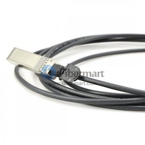
SFP+ direct attach copper cable, also known as twinax cable, is an SFP+ cable assembly used in rack connections between servers and switches. It consists of a high speed copper cable and two SFP+ copper modules. SFP+ copper modules allow hardware manufactures to achieve high port density, configurability and utilization at a very low cost and reduced power budget. SFP+ copper cable assemblies meet the industry MSA for signal integrity performance. The cables are hot-removable and hot-insertable, which means that you can remove and replace them without powering off the switch or disrupting switch functions. A cable comprises a low-voltage cable assembly that connects directly into two SFP+ ports, one at each end of the cable. The cables use high-performance integrated duplex serial data links for bidirectional communication and are designed for data rates of up to 10 Gbps. The following picture shows a Cisco SFP-H10GB-ACU7M compatible 10G SFP+ direct attach copper twinax cable.
Cisco SFP-H10GB-ACU7M Compatible SFP+ Direct Attach Copper Twinax Cable
Types of SFP+ Direct Attach Copper Cables
Generally, SFP+ direct attach copper cable assemblies have two types, SFP+ active direct attach copper cable and SFP+ passive direct attach copper cable.
SFP+ Active Copper Cable: SFP+ active direct attach copper cable assemblies contain low power circuitry in the connector to boost the signal and are driven from the port without additional power requirements. The active version provides a low cost alternative to optical transceivers, and are generally used for end of row or middle of row data center architectures for interconnect distances of up to 15 meters.
SFP+ Passive Copper Cable: SFP+ passive direct attach copper cable assemblies offer high-speed connectivity between active equipment with SFP+ ports. The passive assemblies are compatible with hubs, switches, routers, servers, and network interface cards (NICs) from leading electronics manufacturers like Cisco, Juniper, etc.
Applications of SFP+ Direct Attach Copper Cables
Serial data transmission
Network Interface Cards (NICs)
Data center cabling infrastructure
Fibre Channel over Ethernet: 1, 2, 4 and 8G
10Gb Ethernet and Gigabit Ethernet (IEEE802.3ae)
High density connections between networking equipment
High capacity I/O in storage area networks, and storage servers
InfiniBand standard SDR (2.5Gbps), DDR (5Gbps) and QDR (10Gbps)
Switched fabric I/O such as ultra high bandwidth switches and routers
FAQs of SFP+ Direct Attach Copper Cables
1. Whether active or passive cable assemblies are required?
Active cable assemblies have signal amplification and equalization built into the assembly. They are typically used in host systems that do not employ EDC. Passive cables have no signal amplification in the assembly and rely on host system Electronic Dispersion Compensation (EDC) for signal amplification/equalization.
2. What are the performance requirements for the cable assembly?
Both SFP+ active and passive copper cable assemblies should meet the signal integrity requirements defined by the industry MSA SFF-8431.
3. What cable length and wire gauge are required?
Cable length and wire gauge are related to the performance characteristics of the cable assembly. Longer cable lengths require heavier wire gauge, while shorter cable lengths can utilize a smaller gauge cable. Smaller wire gauges results in reduced weight, improved airflow and a more flexible cable for ease of routing.
4. Are there any special customer requirements?
Examples of special customer requirements include: custom cable lengths, EEPROM programming, labeling and packaging, pull tab length and color, company logo, signal output de-emphasis, and signal output amplitude. You can order custom cables to your specific system architecture.
Conclusion
fiber-mart.com SFP+ twinax copper cables are available with custom version and brand compatible versions. All of them are 100% compatible with major brands like Cisco, HP, Juniper, Enterasys, Extreme, H3C and so on. Both passive twinax cables in lengths of 1, 3 and 5 meters, and active twinax cables in lengths of 7 and 10 meters are available. And the lengths can be customized up to the your requirements. You can get high quality compatible SFP+ cables and worldwide delivery from fiber-mart.com.