12 Ports LC Panduit Opticom Compatible Fiber Adapter Panels (FAPs)

https://www.fiber-mart.com/12-ports-lc-panduit-opticom-compatible-fiber-adapter-panels-faps-p-874.html


FM SKU#:SKU00009Y1
Model#:FAP-SMM-12LCSDX
MFG PART#:

12 Ports LC Panduit Opticom Compatible Fiber Adapter Panels (FAPs) Compatible with:

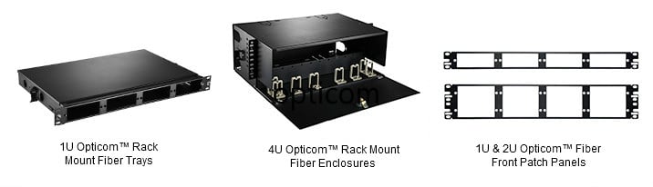
Panduit Opticom ™ Angled Rack Mount Trays and Fiber Adapter Patch Panels

    • 1RU FMT1A with CFAPPBL1A
    • 2RU FMT2A with CFAPPBL2A


    • Opticom ™ Standard Rack Mount Trays and Fiber Adapter Patch Panels


    • 1 RU FMT1 with CFAPPBL1
    • 2 RU FMT2 with CFAPPBL2


    • Opticom ™ Rack Mount Enclosures


    • 1 RU FRME1U
    • 2 RU FRME2U
    • 3 RU FRME3
    • 4 RU FRME4


    • Opticom ™ Rack Mount Fiber Cassette Enclosures


    • 1 RU FCE1U
    • 1 RU open access FCE1UA
    • 2RU FCE2U
    • 4 RU FCE4U


Dimensions(inch)


Key Features and Benefits


    • Panduit® Opticom® Compatible
    • Meet or exceed TIA/EIA-568-C.3 requirements
    • Provides a complete system solution for connectivity
    • Available in 2,3,4,6,8,12,16,18 ports
    • Horizontal and vertical MPO adapters, LC,Keyed LC, SC, ST
    • TIA/EIA-604 FOCIS compliant or compatible simplex or duplex
    • Allows for the industry’s highest patch field density and fiber counts
    • Assures flexibility and ease of network deployment and moves, adds, and changes
    • Available in compatible with all Panduit LC, SC, ST and MPO fiber adapter panels and cassettes


Fiber-MART.Com LC Panduit Opticom Compatible Fiber Adapter Panels(FAPs)

6 Port LC Panduit Opticom Compatible (FAPs)
Fiber-MART FAPS# FIBER TYPE DUPLEX & SIMPLEX POLISH SPLIT SLEEVERS MFG PART#
FAP-SMM-6LCSDX OS1/OS2 Duplex UPC Zirconia Ceramic FAP6WBUDLCZ
OM1 Duplex UPC Phosphor Bronze FAP6WEIDLC
OM2 Duplex UPC Phosphor Bronze FAP6WBLDLC
OM3/OM4 Duplex UPC Zirconia Ceramic FAP6WAQDLC
UPC Phosphor Bronze FAP6WAQDLCZ
8 Port LC Panduit Opticom Compatible (FAPs)
Fiber-MART FAPS# FIBER TYPE DUPLEX & SIMPLEX POLISH SPLIT SLEEVERS MFG PART#
FAP-SMM-8LCSDX OS1/OS2 Duplex UPC Zirconia Ceramic FAP8WBUDLCZ
OM1 Duplex UPC Phosphor Bronze FAP8WEIDLC
OM2 Duplex UPC Phosphor Bronze FAP8WBLDLC
OM3/OM4 Duplex UPC Zirconia Ceramic FAP8WAQDLC
UPC Phosphor Bronze FAP8WAQDLCZ
12 Port LC Panduit Opticom Compatible (FAPs)
Fiber-MART FAPS# FIBER TYPE DUPLEX & SIMPLEX POLISH SPLIT SLEEVERS MFG PART#
FAP-SMM-12LCSDX OS1/OS2 Duplex UPC Zirconia Ceramic FAP12WBUDLCZ
Simplex UPC Zirconia Ceramic FAP12WBULCZ
OM1 Duplex UPC Phosphor Bronze FAP12WEIDLC
OM2 Duplex UPC Phosphor Bronze FAP12WBLDLC
OM3/OM4 Duplex UPC Phosphor Bronze FAP12WAQDLC
UPC Zirconia Ceramic FAP12WAQDLCZ
Simplex UPC Zirconia Ceramic FAP12WAQLCZ


Any Type Any Size All at Fiber-MART.Com

    • Fiber-Mart offers Panduit compatible adapter plates for use in many of our inside and outside plant enclosures.
    • CMultimedia modular panels allow customization of installation for applications requiring integration of fiber optic and copper cables.
    • Opticom® Fiber Optic Adapter Panels (FAPs) are used with Opticom® Rack and Wall Mount Enclosures, Fiber Adapter Patch Panels, and Opticom® Zero RU Fiber Adapter Panel
    • As the best OEM Fiber Adapter Panel manufacturer, Fiber-Mart provides a wide range of quality Fiber Adapter Panel with detailed specifications displayed for your convenient selecting.


    • MAKE TO ORDER (Options)


Connector Dimension Fibers Polish Fiber Type Pack Material Color
  • • LC
  • • SC
  • • ST
  • • MTRJ
  • • MPO
  • • Blank
  • • Unloaded
  • • Customized
  • • 4 fibers – 24 fibers
  • • APC
  • • UPC
  • • Simplex
  • • Duplex
  • • 3 pack
  • • 4 pack
  • • 6 pack
  • • 8 pack
  • • 12 pack
  • • 16 pack
  • • 18 pack
  • • N/A
  • • Metal
  • • Zirconia Ceramic
  • • Phosphor Bronze
  • • Beige
  • • Blue
  • • Green
  • • Yellow
  • • Aqua
  • • Black
  • • Red

For assistance customizing your Adapter Panel, please call us at +86-1-86-2786-1199 or email to sales@fiber-mart.com.

Packaging of Fiber Adapter Panels


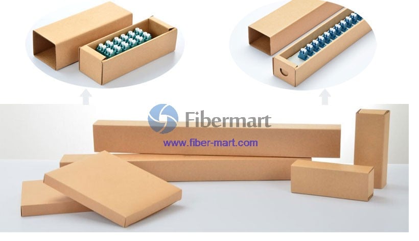
Fiber-Mart provides exquisite appearance, high quality packaging for fiber adapter panels at different sizes, this packaging can protect your product from getting damaged largely. What’s more,the logo on the packaging can be customized as requirement.


Application Multimode
Connector Type LC
No. of Port 12 Ports
Color Aqua
Material of Plates C.R.S. Powder Coated
Material of Sleeves Zirconia Ceramic
Finish Powder Coated in Central Office(Black)
FAP Orientation Horizontal
Vertical
Dimensions(inch) 4.30*1.39*1.73(L*W*HD)
Package Carton


Notes:

  • If customized, please contact at sales@fiber-mart.com

Why Fiber Cabling Is Predominantly Accepted Today

by http://www.fiber-mart.com

Copper wires and cables accompanied us in telecommunication for the past so many years. It was an excellent medium of communication or get linked to feel happy. Gradually technology brought out more complex steps to achieve out individuals the quickest mode not minding the geographical boundaries.
With the time, technology introduced fiber optic rather than copper wire. Now individuals are experiencing the gift of technology knowingly or unknowingly. Telephone cabling, fiber cabling, and cabling services are helping people to enjoy communication too the fullest. As a result if we go back within the good reputation for telecommunication we once had fiber connectivity.
Fiber cabling wasn’t whatsoever new concept entirely. It had been available through cabling services long since. But now it’s been prevailed more dominantly. Development and research have proved that this cabling is highly economical. Hence every company has started adopting this cabling system. The potential studies have successfully increased the capacity of these fiber cabling. Now it’s been increased exhaustively. Fiber cabling services are simple and easy , comfortable to make use of and the price is highly affordable. Both of these properties of fiber cabling forced telecommunication fraternity to adopt fiber cabling happily.
Fiber cabling has become the spinal cord in cabling services or cabling systems worldwide. Now let’s have a look on its advantages. Fiber cabling safeguards your security all the 4 sides. This quality helps government organizations and bank very much where security is a main concern. Another critical feature is speed where data could be transmitted. This selection is very advantageous to health care industry. So hospitals install this fiber cabling because of the result it produces. It has been proved life saving in many of cases.
Fiber cabling also acts as intrusion prevention in cabling services or cabling systems. It can protect your cabling all sorts of intrusion. Fiber cabling can provide you longer length with smaller diameter clubbed with lightest weight. Installation and upgrade is very easy. You can get it completed with assistance of a professional. There’s two kinds of fiber cabling you are able to decide based on your requirements. One is single mode fiber and the other one is multimode. Multiple mode has multi paths to achieve its destination. And because the name indicates, single mode only has one road to reach the destination too.
After using a thorough survey, you can choose which one you have to choose. Seek the help of the professional for installation. And let them know what type installation you’ll need particularly, whether indoor installation or out door. Indoor installation means that you needn’t to worry about environmental surroundings disturbances. Fiber cabling, through telephone cabling and cabling services possess a small check list. That’s firstly you have to choose if installing fiber through inner duct would work for you. You will want to decide on the distance. Finally you have to visit method, which method you have to adopt.

Typical Fiber Patch Panel Types On The Market

by http://www.fiber-mart.com

With the Internet of Things on the rise, more and more electric devices such as building automation controls, LED lights are becoming IP enabled and linking to the cabling infrastructure. There may be scenarios where linked data cables are not seen everywhere when connecting all the devices. Instead, a mass of patch cables are terminated in the telecommunication rooms. Technicians choose different fiber optic patch panel types to terminate the data cables and provide access to the cable’s individual fibers for cross-connection. So what are the typical fiber patch panel types on the market? This article will help you find something.
Benefits of Using Fiber Patch Panel
Fiber patch panels provide a convenient way to rearrange data cable connections and circuits. Using fiber patch panels, network technicians can easily connect cable fibers via cross connection, test the patch panel, and connect it to lightwave equipment. These patch panels are also used as a link demarcation point and in labeling the cable’s individual fibers. All in all, using fiber patch panel can achieve cable management including cable identification, and cable pulling.
Typical Fiber Patch Panel Types On The Market
Commonly, typical fiber patch panels are divided in two types, the rack mount and wall mount type.
rack mount
Rack mount patch panel is generally made for standard 19 inch rack mounting. To provide the best products and services to the customers, fiber-mart.COM launches the FHD and FHX series products.
The FHD rack mount fiber patch panels are available in 1U, 2U and 4U rack. They are made of SPCC materials with the sliding types like a drawer. Sliding the panel open allows users to push or pull cables more stable as well as faster. There are trays and splice sleeves, accessories, inside the patch panel, which are designed to hold fiber adapter panels or MPO/MTP cassettes.
ack mount fiber patch panel
fiber-mart.COM releases the 1U FHX rack mount ultra high density fiber enclosure in order to meet the requirements of most extreme fiber density conditions. With 3 independently sliding drawers, it can support 12 port cassettes or panel. Therefore, in 1 rack unit, the FHX ultra rack mount enclosure can handle up to 144 fiber cables connections.
FHX ultra rack mount fiber enclosure
wall mount
Wall mount type is the fiber enclosure that can be mounted on walls. fiber-mart.COM offers FHD wall mount fiber patch panels which have the designs of 2 door 2 adapters and 2 door 4 adapters as the option. It’s usually equipped with high density cassettes fixed on walls. The cassettes are in a space-saving and mountable panel enclosure. Wall mount patch panel benefits from several aspects like space saving. For more details, you can refer to Introduction of FHD Wall Mount Patch Panel.
FHD wall mount fiber patch panel
Advice On Choosing Suitable Fiber Patch Panel Type
Choosing a suitable fiber patch panel type is the wise practice. Port density, rack size and space should be considered when buying fiber patch panel. Both rack mount and wall mount patch panel are the effective measures for cable management. If there is no enough space in network place and not too many fiber cables around, the wall mount fiber patch panel is a better choice. Otherwise, you will need a rack on which you can place your cable panel.
fiber-mart.COM offers different fiber patch panel types with super quality to help customers optimize the telecommunication project. Hope we are the priority selection when you purchase networking equipment.

Things You Should Know About WDM Filter

by http://www.fiber-mart.com

The optical devices most often used to selectively transmit certain wavelengths are called filter, which covers a broad range of devices, including attenuators. Filters play important roles in Wavelength Division Multiplexing(WDM) systems, although other technologies also may be used. WDM Filters can separate or combine optical signals carried on different wavelengths in a cost-effective manner.
In the world of optics, “filter” often is a broad term applied to components that filter out part of the incident light and transmit the rest. In WDM systems, the wavelengths that are not transmitted through the filter normally are reflected so they can go elsewhere in the system. Such filters are like mirror shades or one-way mirrors, which reflect most incident light, but transmit enough for you to see through them.
Common optical filters accommodate channel growth without service interruption. In addition, the filters’ low network-to-express loss allows stacking, which is essential for scaling new wavelengths. Most filters are equipped with an express port to pass through non-dropped/added WDM channels. Interconnecting express ports of two filters forms an Optical Add/Drop Multiplexer (OADM) with east/west fiber connections. High filter isolation eliminates disruptive “shadow” wavelengths and allows channels that have been dropped at a node to be used elsewhere downstream.
Interference filters and other technologies can be used to separate and combine wavelengths in WDM systems. Several approaches are now competing for WDM applications, some technologies appear to have advantages for certain types of WDM systems, but the field is still evolving, and no single approach dominates. Although these technologies work in different ways, they can achieve the common goal of optical multiplexing and demultiplexing.
There are three competing filtration technologies: Thin Film Filters (TFF), Array Waveguides (AWG), and Fiber Bragg Gratings (FBG). Thin film filters were adopted very early and have been widely deployed because they have the unique attributes that meet the stringent requirements of optical communication systems.
Wide band WDM filters – They are used in EDFAs as pump couplers and supervisory channel monitors. This family of filters covers a wide variety of other filters. Their applications range from CWDM (Coarse WDM), to bi-directional transceivers, to 1310/1490/1550 nm tri-band filters for fiber to the home (FTTH).
Fiber Bragg gratings work similarly by reflecting specific wavelengths. WDM applications require the use of many interference filters or fiber gratings, with each one picking off an individual wavelength or group of wavelengths.
FTTX Filter WDM module is based on thin film filter technology. FiberStore Filter-Based WDM product family covers following wavelength windows commonly used in optical fiber systems: 1310/1550nm (for WDM or DWDM optical communications), 1480/1550nm (for high-power DWDM optical amplifier/EDFA), 1510/1550nm (for DWDM multi-channel optical networks) and 980/1550nm (for high performance DWDM optical amplifier/EDFA) and 1310/1490/1550nm (for PON/FTTX/test instrument). Compared with fused fiber WDM couplers, filter-based WDM components have much wider operating bandwidth, lower insertion loss, higher power handling, high isolation, etc.

How DWDM System Components Work Together with DWDM Technology

by http://www.fiber-mart.com

As DWDM system is composed of these five components, how do they work together? The following steps give out the answer (also you can see the whole structure of a fundamental DWDM system in the figure below):
1. The transponder accepts input in the form of a standard single-mode or multimode laser pulse. The input can come from different physical media and different protocols and traffic types.
2. The wavelength of the transponder input signal is mapped to a DWDM wavelength.
3. DWDM wavelengths from the transponder are multiplexed with signals from the direct interface to form a composite optical signal which is launched into the fiber.
4. A post-amplifier (booster amplifier) boosts the strength of the optical signal as it leaves the multiplexer.
5. An OADM is used at a remote location to drop and add bitstreams of a specific wavelength.
6. Additional optical amplifiers can be used along the fiber span (in-line amplifier) as needed.
7. A pre-amplifier boosts the signal before it enters the d e muliplexer.
8. The incoming signal is demultiplexed into individual DWDM wavelengths.
9. The individual DWDM lambdas are either mapped to the required output type through the transponder or they are passed directly to client-side equipment.
DWDM System Structure
Using DWDM technology, DWDM systems provide the bandwidth for large amounts of data. In fact, the capacity of DWDM systems is growing as technologies advance that allow closer spacing, and therefore higher numbers, of wavelengths. But DWDM is also moving beyond transport to become the basis of all-optical networking with wavelength provisioning and mesh-based protection. Switching at the photonic layer will enable this evolution, as will the routing protocols that allow light paths to traverse the network in much the same way as virtual circuits do today. With the development of technologies, DWDM systems may need more advanced components to exert greater advantages.

DWDM System Components

by http://www.fiber-mart.com

A DWDM system generally consists of five components: Optical Transmitters/Receivers, DWDM Mux/DeMux Filters, Optical Add/Drop Multiplexers (OADMs), Optical Amplifiers, Transponders (Wavelength Converters).
Optical Transmitters/Receivers
Transmitters are described as DWDM components since they provide the source signals which are then multiplexed. The characteristics of optical transmitters used in DWDM systems is highly important to system design. Multiple optical transmitters are used as the light sources in a DWDM system. Incoming electrical data bits (0 or 1) trigger the modulation of a light stream (e.g., a flash of light = 1, the absence of light = 0). Lasers create pulses of light. Each light pulse has an exact wavelength (lambda) expressed in nanometers (nm). In an optical-carrier-based system, a stream of digital information is sent to a physical layer device, whose output is a light source (an LED or a laser) that interfaces a fiber optic cable. This device converts the incoming digital signal from electrical (electrons) to optical (photons) form (electrical to optical conversion, E-O). Electrical ones and zeroes trigger a light source that flashes (e.g., light = 1, little or no light =0) light into the core of an optical fiber. E-O conversion is non-traffic affecting. The format of the underlying digital signal is unchanged. Pulses of light propagate across the optical fiber by way of total internal reflection. At the receiving end, another optical sensor (photodiode) detects light pulses and converts the incoming optical signal back to electrical form. A pair of fibers usually connects any two devices (one transmit fiber, one receive fiber).
DWDM systems require very precise wavelengths of light to operate without interchannel distortion or crosstalk. Several individual lasers are typically used to create the individual channels of a DWDM system. Each laser operates at a slightly different wavelength. Modern systems operate with 200, 100, and 50-GHz spacing. Newer systems support 25-GHz spacing and 12.5-GHz spacing is being investigated. Generally, DWDM transceivers (DWDM SFP, DWDM SFP+, DWDM XFP, etc.) operating at 100 and 50 GHz can be found on the market nowadays.
DWDM Mux/DeMux Filters
Multiple wavelengths (all within the 1550 nm band) created by multiple transmitters and operating on different fibers are combined onto one fiber by way of an optical filter (Mux filter). The output signal of an optical multiplexer is referred to as a composite signal. At the receiving end, an optical drop filter (DeMux filter) separates all of the individual wavelengths of the composite signal out to individual fibers. The individual fibers pass the demultiplexed wavelengths to as many optical receivers. Typically, Mux and DeMux (transmit and receive) components are contained in a single enclosure. Optical Mux/DeMux devices can be passive. Component signals are multiplexed and demultiplexed optically, not electronically, therefore no external power source is required. The figure below is bidirectional DWDM operation. N light pulses of N different wavelengths carried by N different fibers are combined by a DWDM Mux. The N signals are multiplexed onto a pair of optical fiber. A DWDM DeMux receives the composite signal and separates each of the N component signals and passes each to a fiber. The transmitted and receive signal arrows represent client-side equipment. This requires the use of a pair of optical fibers; one for transmit, one for receive.
Bi-Directional DWDM Mux/DeMux Operation
Optical Add/Drop Multiplexers
Optical add/drop multiplexers (i.e. OADMs) have a different function of “Add/Drop”, compared with Mux/DeMuxfilters. Here is a figure that shows the operation of a 1-channel OADM. This OADM is designed to only add or drop optical signals with a particular wavelength. From left to right, an incoming composite signal is broken into two components, drop and pass-through. The OADM drops only the red optical signal stream. The dropped signal stream is passed to the receiver of a client device. The remaining optical signals that pass through the OADM are multiplexed with a new add signal stream. The OADM adds a new red optical signal stream, which operates at the same wavelength as the dropped signal. The new optical signal stream is combined with the pass-through signals to form a new composite signal.
1-Channel DWDM OADM Operation
OADM designed for operating at DWDM wavelengths are called DWDM OADM, while operating at CWDM wavelengths are called CWDM OADM. Both of them can be found on the market now.