Different fibers and different connectors fiber adapter panels to choose.such as MTRJ patch panel, SC fiber patch panel ST fiber patch panel, FC fiber patch panel, LC fiber patch panel,MTP/MPO Fiber Adapter Panels and Customized Rack-Mount Fiber Patch Panels. Currently ,MTP / MPO cabling system helps ease the migration to 40 / 100G networks,The next step we will have to do is to see if the specific fiber link we are using is working properly.
To finish the test, two technology are required. Required materials needed are a roll of tape and the electric torch. Each technician is stationed at each end of the fiber link, perhaps in two different telecom closets which is where the fibers are usually terminated. Each technician must identify the specific fiber’s connector end, which in most cases is connected to an adapter on the back plane of the Fibre Optic Patch Panel or termination box.the test include the fiber connector (called the ferrule) directly against the electric torch with the light on. it must unlink the fiber connector from the patch panel adapter so that the tip of the fiber can be directly applied to the electric torch’s lens. When unlink the connector and extracting it a short distance from the patch panel, with at least enough slack to reach the electric torch lens. There are two prevalent types of fiber connectors in use today. The ST or round connector disconnects by pushing the connector toward the adapter and turning the connector body counter clockwise ¼ turn and then pulling the connector away from the termination. The SC or square connector is a push-pull termination and can be removed by simply grasping the connector body and pulling it out. In no case should a technician use any hand tools such as pliers to remove the connectors; if you cannot get the connector free by using just your fingers you are not doing the disconnection correctly.
Superiority of MPO/MTP Assemblies
Actual practice proves that MPO/MTP components are superior to other assemblies in high density applications.No tools are required to install the cassette in the panel enclosure, and the push-pull connection offers an easier way to be locked or unlocked in patch panels. recommended MPO/MTP products for high density patching as below.
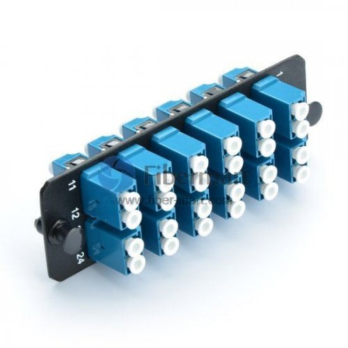
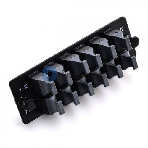
MTP/MPO Fiber Adapter Panel
To efficiently handle the cabling congestion problem associated with 40G/100G network connections, employing a high-density fiber patch panel is proved to be an ideal choice. MTP/MPO fiber adapter panel is designed to assure flexibility and ease of network deployment and facilitate migration from 10G to 40/100G infrastructure. It is used in high-density network applications for cross connects in main distribution, horizontal distribution, and equipment distribution areas. This fiber adapter panel ensures efficient use of space, quick deployment and the highest reliability for the lowest installed cost. Which in turn provide a high return on investment.
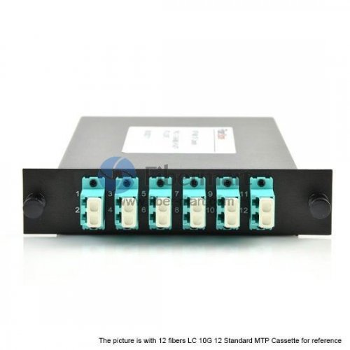
MTP/MPO Cassette
MTP/MPO cassette is the kind of module that allows for rapid deployment of high-density data center infrastructure as well as improved troubleshooting and reconfiguration during moves, adds and changes. Which is proved to be time and energy saving as well as cost efficient. Moreover, it enables users to take the fibers brought by a trunk cable and distribute them to a duplex cable. This cassette modules are fitted with 12 or 24 fibers and have LC, SC or E2000 adapters on the front side and MTP/MPO at the rear.
MPO/MTP Fiber Enclosure
As a scalable modular, the MPO/MTP fiber enclosure is designed for high density Gigabit Ethernet application. MPO/MTP fiber enclosures are used for terminating backbone cables at the main distribution area (MDA) and horizontal distribution area (HDA). They are available in 1U, 2 U and 4U (as shown in the following figure).
Conclusion
Fiber-MART provides a series of MPO/MTP solutions and have a number of different customized options available to fit whatever application you require. With products compatible for trusted brands including Black Box, Wirewerks, Mr-technologies, Corning, Leviton, Panduit Opticom adapter panel and more. For more information, welcome to visit www.fiber-mart.com or contact me by E-mail: service@fiber-mart.com