Advances in communication technology have led to the introduction of a new means of communication that is not only faster, but also more efficient and lighter on the environment. This technology, known as fiber optics, has greatly increased the speed at which people can now communicate. Let’s take a closer look at some of the advantages of fiber optic technology and what makes it the best means of communication.
Immunity
For one, fiber optics is immune from electromagnetic interference. This means that the signal that is sent from one end is the exact same one that is received on the other end. Other factors such as lightning and heavy industries emitting waves have no effect on fiber optics signals, making the technology a very conducive means of communication. Fiber cable signals cannot be interfered with by signals from outside, making them great for sensitive information.
Secure communication
Given the fact that fiber optic cables use light instead of electrical currents for communication, they are more secure when used in communication. It is very difficult to do a fiber optic equivalent of a wiretap since there is a great deal of information that flows through these cables. Fiber optics is much more secure, and when it is used for communication, the information that is passed is protected from tapping by malicious users.
Cables are non-conductive
Fiber optic cables are made of glass or plastic. Both of these materials do not conduct electricity, so they cannot be interfered with using electrical currents. If lightning strikes a fiber optic cable, nothing is distorted in the cable, and communication goes on as usual. This makes fiber optic technology an excellent means of communications, especially in areas where lightning and other natural hazards are common.
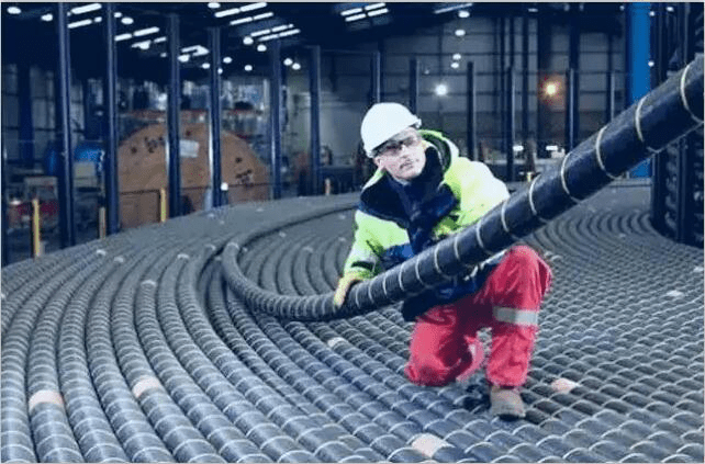
Easy to install
Given the fact that fiber optic cables are just a fraction of the weight of traditional copper cables, they are extremely easy to carry from one location to the other and also easy to install. They need less manpower to install, which means smaller installation costs. The ease of installation also makes the deployment of fiber optic networks easy and much faster. Since fiber optics are lighter, it is very easy to carry them around during the installation process. Leaving them out in the open at night does not expose them to rust and other environmental factors that are experienced by traditional copper cables.
High bandwidth
Since fiber optic cables use light to transmit signals, a lot more information can be carried through the cable. This increased bandwidth can now be used for more efficient communication and transfer much more information. The increased bandwidth means that people can download files much faster and communicate more efficiently.
As you can see, fiber optics technology has made it easier for people to access the internet with a high bandwidth and to get access to information globally.