Fiber Optic Connector Types for data center

by http://www.fiber-mart.com

LC and MPO Fiber Optic connectors were defined for data center applications in accordance with ISO/IEC 24764, EN 50173-5 and TIA-942 standards for fiber optic cabling systems.
MPO Connector (IEC 61754-7)
MPO (multipath push-on) is based on a plastic ferrule that provides the ability to house up to 24 fibers in a single connector. Connectors with up to 72 fibers are already in development by this time. This connector stands out because of its compact design and easy operation, but brings disadvantages in optical performance and reliability.
This connector type is of crucial importance because of its increased packing density and ability to migrate to 40/100 Gigabit Ethernet.optical-fiber-mpo-connector_400
LC Connector (IEC 61754-20)
This connector is part of a new generation of compact connectors. It was developed by Lucent (LC stands for Lucent Connector). Its design is based on a 1.25 mm-diameter ferrule. Its duplex adapter matches the size of an SC adapter. As a result, it can achieve extremely high packing densities, which makes the connector attractive for use in data centers.connector_lc
SC Connector (IEC 61751-4)
SC stands for square connector or subscriber connector. It makes high packing densities possible because of its compact design, and can be combined into duplex and multiple connections. Despite its age, the SC continues to gain in importance because of its outstanding properties. It has been the most important WAN connector worldwide up to today, usually as a duplex version, because of its good optical properties.connector_sc-pc-apc
E-2000™ Connector (LSH, IEC 61753-15)
This connector is a development by the company Diamond SA which specializes in LAN and CATV applications. It is produced by three licensed manufacturers in Switzerland, which has also led to its unequaled quality standard. The integrated protective flap provides protection from dust and scratches as well as laser beams. The connector can be locked using grids and levers which can be coded by color and also mechanically.

Important Criteria for Choosing a Datacenter OTDR

by http://www.fiber-mart.com

With the technological evolution occurring in data centers, test requirements dramatically changed for the fiber networks that connect mission-critical servers, networking and storage devices. Selecting the proper OTDR to test your network not only strengthens its reliability, but also improves how quickly and efficiently the job is done, as well as documenting the quality of work. Here are some recommended criteria to consider, aside from the basic OTDR testing capabilities.
1. A simplified and task-focused user interface: Populating a data center with thousands of tested fibers is an enormously time consuming job. Maintaining fiber health is just as challenging and makes fast troubleshooting critical. Almost every OTDR on the market today is designed to cover carrier applications. As a result, many have very complicated user interfaces, which require the user to grapple with numerous buttons and controls and navigate cumbersome multi-level menus. While this is suitable for the fiber enthusiasts who test Telco fiber on a daily basis, it’s a different story for enterprise network technicians. An OTDR designed around the enterprise workflow,
with an intuitive user interface, greatly improves operating efficiency. Simple-to-use test equipment shortens the learning curve, reduces testing time and ultimately saves money.
2. Precision fiber channel information: With the increasing use of short patch fibers and multi-fiber connectors, details on every link—loss, connector, and reflectance—are critical to ensuring performance. OTDRs with an attenuation dead zone of more than 3 m are no longer applicable for testing datacenter fiber. Ultra-short dead zones are needed to find issues that jeopardize the link loss budget or cause serious signal degradation. In addition, fast problem resolution requires that faults and events be presented in a simple, graphical map so users at various skill levels can efficiently perform fiber troubleshooting and accelerate network recovery.
3. Effective planning and documentation: As data centers grow and change, coordinating projects and ensuring that all fibers are installed with certified quality is challenging. There are a number of software applications available for project management, but until recently none have been integrated with an OTDR. Integrated project management capabilities with cable-by-cable granularity can save time and planning effort. Look for an OTDR with built-in project management capability that allows you to plan day-to-day activities without using a PC or laptop. You should be able to use a single tool to control, monitor, consolidate and document all test results.

WDM Solution

According to the market demand for large transmission capacity in current optical interconnect,network managers are relying more on fiber optics, and requiring more bandwidth and faster transmission rates over ever increasing distances.

According to the market demand for large transmission capacity in current optical interconnect,network managers are relying more on fiber optics, and requiring more bandwidth and faster transmission rates over ever increasing distances.

What is WDM?

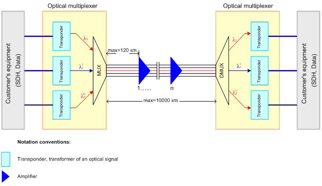
Wavelength Division Multiplexing, WDM, is a technology that increases bandwidth by allowing different data streams at different frequencies to be sent over a single optical fiber network. Signals at WDM wavelengths are independent from each other.

Wave Division Multiplexing (WDM) technologies can increase capacity on the existing fiber infrastructure. WDM is a technology which multiplexes multiple optical signals onto a single fiber by using different wavelengths, or colors, of light. By utilizing WDM communication methods, network managers can realize a multiplicative effect in their available fiber’s capacity.

WDM technology Short for wavelength division multiplexing, WDM is a way of transmitting multiple simultaneous data streams over the same fiber. Since this happens simultaneously, WDM does not impact transmission speed, latency or bandwidth. WDM functions as multiplexing multiple optical signals on a single fiber by using different wavelengths, or colors, of laser light to carry different signals. Network managers can thus realize a multiplication effect in their available fiber’s capacity with WDM.

WDM-technology.jpg

Coarse Wave Division Multiplexing (CWDM)

CWDM increases fiber capacity in either 4, 8, or 18 channel increments. It is a method to maximize existing fiber by decreasing the channel spacing between wavelengths. Since CWDM is a passive technology, Another benefit to the passive CWDM technology is that no configuration is necessary, which makes CWDM a low-cost and effortless technology to implement. The most complex step in CWDM integration is aligning and connecting the patch cables from the correct wavelength optic to the correct port on the multiplexers on each end of the link.

The benefits of CWDM include:

  • Passive equipment that uses no electrical power
  • Extended Temperature Range (0˚C – 70˚C)
  • Lower cost per channel than DWDM
  • Scalability to grow fiber capacity with little or no increased cost
  • Protocol transparent
  • Simple to install and use

Drawbacks of CWDM:

  • 18 channels may not be enough, and fiber amplifier cannot be used with them
  • Passive equipment that has no management capabilities
  • Not the ideal choice for long-haul networks


Dense Wave Division Multiplexing (DWDM)

Dense wavelength division multiplexing (DWDM) is a technology that puts data from different sources together on an optical fiber, with each signal carried at the same time on its own separate light wavelength. Using DWDM,  is a layer-1 transport technology that multiplexes several optical signals into the same fiber by using different wavelengths (colors). It allows you to transport more data across existing dark fiber infrastructure.up to 80 (and theoretically more) separate wavelengths or channels of data can be multiplexed into a light-stream transmitted on a single optical fiber.

DWDM_анг.JPG

Benefits of DWDM:

  • Transparency: due to that DWDM is with a physical layer architecture, it can transparently support both TDM and data formats such as ATM, Gigabit Ethernet, ESCON, and Fibre Channel with open interfaces over a common physical layer.
  • Scalability: DWDM can leverage the abundance of dark fiber in many metropolitan area and enterprise networks to quickly meet demand for capacity on point-to-point links and on spans of existing SONET/SDH rings.
  • Dynamic provisioning: fast, simple, and dynamic provisioning of network connections give providers the ability to provide high-bandwidth services in days rather than months.


Drawbacks of DWDM:

  • DWDM solutions are quite expensive
  • Active DWDM solutions require a lot of set-up and maintenance expense

CWDM Mux / Demux

Using CWDM multiplexing technology paired with wavelength specific optics in Transition Networks’ fiber optic devices and switching products allows you to realize the full benefit of CWDM technology. The modular approach that Transition Networks takes toward CWDM deployments makes scaling a project to fit your exact needs easy and affordable. Transition Networks also offers products that optimize standard fixed optic wavelengths on existing products by converting them to the appropriate CWDM “color” or wavelength.


DWDM Mux / Demux

the common configuration of DWDM Mux/Demux is from 8 to 96 channels. Maybe in future channels can reach 200 channels or more. DWDM system typically transports channels (wavelengths) in what is known as the conventional band or C band spectrum, with all channels in the 1550nm region. The denser channel spacing requires tighter control of the wavelengths and therefore cooled DWDM optical transceiver modules required, as contrary to CWDM which has broader channel spacing un-cooled optics, such as CWDM SFP, CWDM XFP.

To sum it up, With DWDM Mux/DeMux, single fibers have been able to transmit data at speeds up to 400Gb/s.  there is no doubt that DWDM technology will reshape the future communication network by virtue of its various advantages and applications in many aspects.To expand the bandwidth of your optical communication networks with lower loss and greater distance capabilities.

WDM solution capacity expansion in a more cost-effective, simplified and flexible way.Fiber-MART can help you to choose the right WDM solution.Any question pls feel free to contact us .E-mail: Service@fiber-mart.com

Cable Management Procedures

by http://www.fiber-mart.com

Sound cable management practices help data centers function smoothly and reliably. Managers can implement a variety of procedures to minimize data center inefficiencies, such as slow troubleshooting and interruptions due to the unplugging the wrong equipment.) Well managed cable supports server performance and throughput, minimizes disruptions and downtime, and safeguards the integrity of cables and ports.
One solution for complex networks is the use cable management systems (CMSs). There are many products and services available that managers can use to document cable sub-systems and paths, plan migrations and expansions, and track moves, adds and changes (MACs). The software requires manual entry of cable connections and types, and users must make updates for each move or change to keep documentation accurate. Some CMSs can model data center equipment and migrations and generate task lists for migration.
Horizontal and Vertical Management
Where Main Distribution Areas (MDAs) connect to Horizontal Distribution Areas (HDAs) and then to Equipment Distribution Areas (EDAs), managers need to deploy sturdy, reliable components that support high density, are easy to install, provide adequate spacing between ports, and can handle heavy cable bundles. The horizontal cable manager units are made of metal or heavy plastic. Choose pieces that are best-suited for the cable types and quantities within each rack. Dust covers are appropriate if there is little likelihood of MACs but can get in the way during re-cabling.
When choosing vertical management components, plan for ease of access and allow room for both patch cable slack and future increases in cable density. Use vertical and horizon- tal components that allow for acceptable bend radiuses, so that cables and ports are not damaged over time.
Cabinet Selection
Network or telecommunications cabinets can simplify monitoring and troubleshooting by making switches and patch panels easy to view. Cabinets come in different heights (typically 6U to 15U) to accommodate multiple layers of 19-inch equipment and are wall-mounted to support heavy equipment. They typically include the wall-mount section and the cabinet itself, which is attached to the wall mount and has a Plexiglas front that allows monitoring without opening the cabinet. Doors are reversible to improve usability in tight spaces.
When setting up a cabinet, installers should populate the bottom sections first and add panels upwards from there. There should be sufficient openings to enable airflow, and fans should be added as needed. Locking options are available for secure installations, and there are options to add shelves and/or drawers.

Overview of 100G QSFP28 Optical Transceivers

by http://www.fiber-mart.com

QSFP28 fiber optic module has become the dominant form factor for 100G high-speed networks. The interconnect offers multiple channels of high-speed differential signals with data rates ranging from 25Gbps up to potentially 40Gbps, and meets 100Gbps Ethernet (4×25Gbps) and 100Gbps 4X InfiniBand Enhanced Data Rate (EDR) requirements. Fiber-mart 100G QSFP28 optical transceiver including SR4, LR4, PSM4, CWDM4 and AOCs, complied with IEEE 802.3bm and SFF-8636, compatible with network device from different vendors, designed for applications of 100G Data Center Internal Network, Data Center Interconnection and Metro Network.
The following list is QSFP28 fiber optic transceivers form Fiber-mart.com, it is able to compatible with the main network device provider like Cisco, HPE, Huawei, etc.
QSFP28 SR4: The QSFP28-SR4 optical module supports links of 70m over OM3 MMF and 100m over OM4 MMF with MPO-12 or MTP-12 connectors. This transceiver is a parallel 100G QSFP28 optical module with 4 independent transmit and receive channels each capable of 25Gb/s operation. The 100G QSFP28-SR4 modules are ideal for rack to rack connections in the datacenter and short reach telecom applications.The QSFP28-100G-eSR4 is extended version of QSFP for transmit over 300m.
QSFP28 PSM4: The 100G PSM4 specification defines requirements for a point-to-point 100 Gbps link over eight single mode fibers (4 transmit and 4 receive) of at least 500m, each transmitting at 25Gbps. Four identical and independent lanes are used for each signal direction. PSM4 does not need a MUX/DEMUX for each laser but it does need either a directly modulated DFB laser (DML) or an external modulator for each fiber. With an MTP interface, PSM4 modules can bus 100Gbps point-to-point over 2km or can be broken out into dual 50Gbps or quad 25Gbps links for linking to servers, storage and other subsystems.
QSFP28 CWDM4: The CWDM4 module uses Mux/Demux technologies with 4 lanes of 25 Gbps optically multiplexed onto and demultiplexed from duplex single-mode fiber. It is centered around the 1310nm band with 20nm channel spacing as defined by the ITU standard. With a reach of 2km, QSFP28 CWDM4 transmits 100G optical signals via a duplex LC interface.
QSFP28 LR4: This module is for longer span 100GbE deployment, such as connectivity between two buildings, QSFP28-LR4 with duplex LC fiber interface and transmitted over single-mode fiber cable. This LR4 module uses WDM technologies to achieve 100G transmission over four different wavelengths around 1310nm. It can support distances up to 10km.
QSFP28 ER4 Lite: QSFP28-ER4 Lite is a 100Gbps transceiver designed for optical communication applications compliant to Ethernet 100GBASE-ER4 Lite standard. The high performance cooled LAN WDM EA-DFB transmitters and high sensitivity APD receivers provide superior performance for 100Gigabit Ethernet applications up to 25km links without FEC and 32km links with FEC.

WDM, Mux/Demux and OADM Over view

by http://www.fiber-mart.com

CWDM Mux/Demux
The Coarse Wavelength Division Multiplexing-CWDM Mux/Demux is often a flexible plug-and-play network solution, which helps insurers and enterprise companies to affordably implement denote point or ring based WDM optical networks. CWDM Mux/demux is perfectly created for transport PDH, SDH / SONET, ETHERNET services over WWDM, CWDM and DWDM in optical metro edge and access networks. CWDM products are popular in less precision optics and lower cost, un-cooled lasers with lower maintenance requirements. Weighed against DWDM and Conventional WDM, CWDM is much more economical and less power consumption of laser devices. CWDM Multiplexer Modules can be found in 4, 8 and 16 channel configurations. These modules passively multiplex the optical signal outputs from 4 too much electronic products, send on them someone optical fiber and after that de-multiplex the signals into separate, distinct signals for input into gadgets across the opposite end for your fiber optic link.

DWDM Mux/Demux
The Dense Wavelength Division Multiplexing-DWDM Mux/Demux Modules are made to multiplex multiple DWDM channels into one or two fibers. Based on type CWDM Mux/Demux unit, with optional expansion, can transmit and receive as much as 4, 8, 16 or 32 connections of various standards, data rates or protocols over one single fiber optic link without disturbing one another. DWDM MUX/DEMUX modules offers the most robust and low-cost bandwidth upgrade on your current fiber optic communication networks.

OADM Add/Drop Multiplexer

WDM OADM Add/Drop Multiplexer is designed to organize the signal output at a predetermined wavelength from an optical line in the WDM system. These devices are called Add/Drop modules — WDM OADM (Optical Add/Drop Multiplexer).

The OADM module, extracting the desired signal, passes the rest of the emission unchanged. OADM modules are passive devices. Single-sided and dual-sided modules have a fundamental difference. Single-sided OADM can seize and add a signal in the line towards one multiplexer. Dual-sided OADM can establish a connection with two multiplexers, and the line will have no idle channels.