The Top 5 structured fiber optic cabling faults

by http://www.fiber-mart.com

1. Cause: Intermittent faults – Unidentified intermittent faults are amongst the most common and damaging issues that affect structured cabling networks. Faulty patch leads and broken or malfunctioning outlets are typical causes of this frustrating and puzzling problem, but identifying the lead or outlet that’s misfiring can be a headache in itself.

Effect: Valuable resources are wasted.

2. Cause: Wi-Fi problems – Wi-Fi can present a host of challenges when installed incorrectly – from poor coverage to intermittent connectivity. Connecting multiple devices that use conflicting Wi-Fi standards is a common cause of many problems. Equally, the Wi-Fi devices themselves may be faulty or installed in the wrong position. If neither of these factors are the cause of your issues, check if you’ve connected new Wi-Fi devices with outdated cabling.

Effect: Workforce efficiency and productivity plummet.

3. Cause: Disorganization and disorder – Structured cabling networks often become disorderly over time as multiple firms are called in to install, maintain and repair them, resulting in a confused and jumbled system. A disorganized structured cabling network can also be the result of sloppy workmanship, where engineers haven’t taken enough care during the implementation process. Untidy patching, inaccurate labelling and poor record keeping are all warning signs that shouldn’t be ignored.

Effect: Unnecessary expenditure.

4. Cause: Mismatched cabling – Even if your infrastructure is built on one category of cable, if two different manufacturers have supplied different elements of your network, you may encounter problems. A structured cabling network that isn’t consistent end-to-end can cause electrical mismatching between components and although this can be difficult to spot, the effects are plain to see.

Effect: Costly network challenges.

5. Cause: A lack of network redundancy – Organizations need a backup cabling network and an uninterruptable power supply (UPS) to ensure connectivity and power remain consistent when the lights go out unexpectedly. This is especially true of critical links and services that underpin crucial business operations, for example the structured cabling network that supports a bank’s trading floor. Despite the importance of these systems, we find that many organizations don’t consider installing them until after an incident has taken place.

Effect: A catastrophic loss of service.

What does an Optical Attenuator do ?

With the advancement of DWDM technology, as well as the potential to flexibly upgrade the reconfigurable optical add-drop multiplexer (ROADM), the demand for optical attenuator is sure to soar, especially for optical variable attenuator.

With the advancement of DWDM technology, as well as the potential to flexibly upgrade the reconfigurable optical add-drop multiplexer (ROADM), the demand for optical attenuator is sure to soar, especially for optical variable attenuator.


Optical Attenuators, or fiber optic attenuators, are used in optical communications to reduce optical fiber power at a certain level. Generally, the attenuator types are classified by connector types and attenuation levels. A common version is the female to male plug type bulkhead attenuator which has a connector at one side and a adapter at the other side.in fiber optics, attenuation can also be called transmission loss. It’s the reduction in light signal intensity with regards to the distance traveled by the signal inside a transmission medium. Attenuation is an important element to limit the transmission of the digital signal driving considerable distances. Optical attenuator reduces this optical signal because it travels along a totally unoccupied space or perhaps an optical fiber.

atten2

Optical fiber attenuators may employ several principles when utilized in fiber optic communications. One common principle may be the gap loss principle. Attenuators by using this principle are responsive to the modal distribution ahead of the attenuator. Thus, they should be utilized at or close to the transmitting end. Otherwise, the attenuators could establish less loss than intended. This problem is avoided by attenuators which use absorptive or reflective principles

Types of Fiber Optic Attenuators:

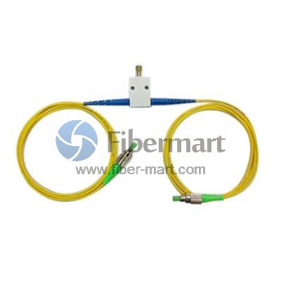
Optical attenuator takes a number of different forms. They are typically grouped as fixed optical attenuator and optical variable attenuator

The fixed attenuator, as the name implies, has a fixed attenuation level. Fixed attenuator can theoretically be designed to provide any amount of attenuation that is desired and be set to deliver a precise power output. Fixed attenuators are typically used for single-mode applications. They mate to regular connectors of the identical type for example FC, ST, SC and LC.

variable optical attenuators (VOA) resistors are replaced with solid state devices like the metal semiconductor field effect transistor (MESFETs) and PIN diodes. VOA attenuates light signal or beam inside a guarded manner. Thus producing an output optical beam with various attenuated intensity. The attenuator adjusts the ability ratio between your bright beam from the tool and the light beam entering the device over a changeable rate. VOA is usually used in fiber optic communication systems to manage optical power levels in order to prevent damages in optical receivers which may be due to irregular or fluctuating power levels. Price of commercial VOA varies depending on the manufacturing technology used.

Working Principle of Optical Attenuator

Optical attenuator usually works by absorbing the light, like sunglasses absorb the extra light energy. It typically has a working wavelength range in which it can absorb the light energy equally. It should not reflect the light since that could cause unwanted back reflection in the fiber system. Another type of attenuator utilizes a length of high-loss optical fiber, that operates upon its input optical signal power level in such a way that its output signal power level is less than the input level. The power reduction is done by such means as absorption, reflection, diffusion, scattering, deflection, diffraction, and dispersion, etc.


Applications of Optical attenuators 

A set optical attenuator fixed amount of attenuation of the optical road to the sunshine energy is principally used for its excellent temperature characteristics. Within the commissioning from the system, widely used in analog optical signal through the corresponding period of optical fiber attenuation or reduce the margin from the optical power the relay station may also be used to prevent saturation from the optical receiver; optical test instrument calibration scaling. For different line interface, you can use different fixed attenuator; if the interface is really a pigtail type available pigtail type optical attenuator welded towards the optical path between the two sections of fiber; If you are debugging the machine connector interface converter or inverter-type fixed attenuator.

Fiber optic attenuator is an essential passive component in the optical communication system. In practical applications often require attenuation quantity of the optical attenuator could be changed using the user needs. Fiber-Mart provides optical attenuators with various connector types, such as FC/SC/ST/LC/E2000, available with APC or UPC polish. Our fixed attenuators can be with different attenuation levels from 1 dB to 30 dB (step by 1 dB), while the variable optical attenuators (generally used as in-line attenuators) can be with a range of 0 ~ 60 dB. Customers can buy these attenuators directly in this category or Make Customized Orders. Any question pls feel free to contact us. E-mail: service@fiber-mart.com


FAQ about 100G Ethernet Transmission

by http://www.fiber-mart.com

What standard addresses 100G, and when will this standard be complete?
The IEEE 802.3ba technical requirements were ratified in the recent April 2010 sponsor ballot. The document has been forwarded for approval to RevCom and is expected to be released in June 2010.

When is customer implementation of 100G expected?
Early end-user adoption is expected in 2010. Industry adoption is anticipated in 2013.

Where will 100G be used (in what applications)?
Core networking applications will have a future need for bandwidth beyond existing capabilities. Switching, routing and aggregation in data centers, internet exchanges and service provider peering points, and high-bandwidth applications such as video-on-demand and high-performance computing environments will drive the need for 100 Gb/s Ethernet interfaces.

What parameters affect a product’s ability to support 100G? Which of these is the limiting factor?
Bandwidth and insertion loss each impact the ability to meet the standard’s transmission distance of at least 100 meters over OM3 fiber and 150 meters over OM4 fiber. The transceiver specifications impact distance, transceiver cost and the amount of loss allocated for the fiber and connectors in the system. For products that meet the bandwidth and the cable fiber skew performance criteria, system loss will be the limiting factor in transmission distance.

What are the distances and insertion loss budgets for 100 GbE?
For multimode systems, 40 and 100 Gigabit Ethernet specify a minimum distance of 100 meters over OM3 fiber and 150 meters over OM4 fiber. OM3 and OM4 are the only multimode fiber types included in the standard. The OM3 and OM4 channel loss budgets are 1.9 dB that includes a 1.5 dB total connector loss and 1.5 dB that includes a 1.0 dB total connector loss, respectively.

What transmission method will be used for 40G and 100G?
Parallel optics transmission has been adopted for 40 and 100 Gigabit Ethernet over OM3 and OM4 fibers. Parallel optics transmission, compared to traditional serial transmission, uses a parallel optical interface where data is simultaneously transmitted and received over multiple fibers. The 40 Gigabit interface utilizes 4 x 10 Gigabit Ethernet channels on four fibers per direction. The 100 Gigabit interface utilizes 10 x 10 Gigabit Ethernet channels on 10 fibers per direction.

What is skew?
Skew is the difference in time of flight between light signals traveling on different fibers. This is relevant to the 100 Gigabit Ethernet standard that uses parallel optics. In parallel optic systems, one data stream is divided into multiple data streams and transmitted over different optical fibers to enable lower-cost transceivers to be used.

The IEEE 802.3ba standard has a cabling skew of 79 ns. Corning Cable Systems has done internal skew testing on 100G Ready Products that demonstrated compliance to a strict 0.75 ns skew requirement as defined in the InfiniBand Standard. Deployment of a connectivity solution with strict skew performance ensures compatibility of the cabling infrastructure across a variety of applications. When evaluating optical cabling infrastructure solutions for 40/100G applications, selecting one that meets the 0.75 ns skew requirement ensures performance not only for 40/100G, but for InfiniBand and future Fibre Channel data rates of 32G and beyond. Additionally, low-skew connectivity solutions validate the quality and consistency of cable designs and terminations to provide long-term reliable operation.

How will polarity work for 100G?
The CXP transceiver will be utilized for 100G transmission. The CXP transceiver has 10 transmit and 10 receive optical lane positions as depicted in Figure 1. The CXP transceiver contains 24 total positions arranged in two rows of 10 or 12 positions. One row is dedicated to transmit optical lanes and the other row to receive optical lanes. A 24-fiber MTP® Connector interfaces with the CXP transceiver. Plug & Play™ Universal Systems trunks are compatible with the CXP transceiver polarity requirements.

What about 40G transmission?
The IEEE standard addresses both 40G and 100G Ethernet transmission, so similar parameters apply. 100G Ready solutions are backwards-compatible with 40G.

Introduction to Active Optical Cable (AOC Cable)

by http://www.fiber-mart.com

226f6963924fc3c5e6ac066efe76103a.image.300x300

Data requirement is tremendous increase in year 2016 to year 2020, thus a high transmission media is required, Active Optical Cables (AOCs) could achieve high data transmission over distances, The AOC with electrical inputs as a traditional copper cable, and use optical fiber as transmission media, it is an ideal to streamlined installation for high-performance computing and storage applications with sacrificing compatibility of the existing standard electrical interfaces.
The AOC Cable generally composed  as follow:
The Active connectors are QSFP+, complied with SFF-8436 standard, could be hot-swappable in switch, router, etc.
The system with 4Tx and 4 Rx channels, could transmit data in parallel to reach duplex data transmission.
The AOC with O-E (Optical-Electronic) and E-O (Electronic – Optical) conversion module.
The ribbon optical fiber cable (generally yellow cable for SM (single mode) Cable, and Orange or Aqua for Multimode Cable).
Why Use Active Optical Cable (AOC)?
1. Compared to Copper Cables
Longer reach, using single mode fiber, could transmit over kilo meters
Lower weight and tighter bend radius, compared with traditional bulky  cooper cable, the cable is light weight and with small bending radius, easy for installation, as well as enable simpler cable management
Thinner cables, It allows better airflow for cooling
Lower power consumption
No need for power-hungry conditioning ICs on the host board
2. Compared to Optical Transceivers
Cost effective: Compatible with existing cooper interface, no need new investment
Data center/Consumer friendly: No need to worry about contamination on fiber connector
Disadvantage: Have to use extra cabinets for wiring, not able to use fiber optic patch panel

Introduction to OSFP Optical Transceiver

by http://www.fiber-mart.com

580248b14f42d3ec505a05812693f404.image.300x300

OSFP is short for Octal Small Form Factor Pluggable. it is being designed to use eight electrical lanes and each lane for 50GBE to deliver 400GbE. compared with QSFP transceiver, It is slightly wider and deeper, but it still supports 36 OSFP ports per 1U front panel, enabling 14.4 Tbps per 1U.
OSFP is a conventional style of electrical interconnect, leveraging best practices that the industry has learned in the past from SFP and QSFP connectors. The electrical connector in OSFP has a single row of contacts on both top and bottom, and it provides robust electrical and signal-integrity performance. Because it’s faceplate pluggable and eld replaceable, it has a single-receptacle electrical connector.
One of the nontraditional aspects of OSFP is that it integrates thermal management (heat sinking) directly into the form factor to help cool the module, similar to the microQSFP form factor that predates it. An OSFP integrated heat sink is intended to enable modules with up to 15 W of power in a switch chassis with conventional front-to-back air ow. This accomplishes two things over a more conventional riding heat sink: It eliminates the high thermal resistance between the module and the heat sink, and, secondarily, once the air exits the back of the module form factor, it is available for cooling the silicon switch or compute chips that are downstream inside the equipment enclosure.
The OSFP receptacle does not offer backwards intermate-ability to existing modules since it favors optimizing the electrical, packaging, and thermal aspects over legacy application support.
There are multiple type of connectors supported by OSFP; Duplex LC, MPO/MTP, CS, and copper.

ST Connector Introduction

by http://www.fiber-mart.com

The ST connector (Straight Tip or Bayonet Fiber Optic Connector ), mainly applied in Multimode, rarely single-mode, complied with IEC 61754-2, the ST Connector features a 2.5 mm ferrule with a quick release bayonet (stick and twist) style body for ease of use. ST connectors are available for single mode UPC with yellow boots, APC with green boots and multimode PC with black or red boots suitable for either 900µm, 2.0mm or 3.0mm cable diameters.connector_st
Features
Complies with IEC 61754-2 and TIA 604-2-B, FOCIS-2
Low insertion loss and back reflection capability
Bayonet style (stick and twist) housing for easy connection
Nickel plated metal body
Zirconia ceramic ferrule available in several performance grades
RoHS materials, REACH SvHC compliant
Individual parts packed in bulk package
Applications
Local area networks
Data processing networks
Distribution application
Premises distribution