Introduction of Fiber Optic Attenuators

Do you know what is the fiber attenuator used for? As we know, the source of the single mode fiber is laser, the power of which is extremely strong. Therefore we can use single mode fiber to achieve long distance transmission. But, if the transmission distance over single mode fiber is too short, too much light may overload a fiber optic receiver, which may cause serious high bit error rates. How to solve this?

Do you know what is the fiber attenuator used for? As we know, the source of the single mode fiber is laser, the power of which is extremely strong. Therefore we can use single mode fiber to achieve long distance transmission. But, if the transmission distance over single mode fiber is too short, too much light may overload a fiber optic receiver, which may cause serious high bit error rates. How to solve this? Fiber attenuator should be inserted at the receiver end to reduce the power to the proper level. This article sheds light on types, and applications of optical attenuators, helping you to choose a right one.

What is Fiber Attenuator?
Fiber optic attenuator is a passive device used to reduce the power level of an optical signal because too much light can overload a fiber optic receiver and degrade the bit error ratio (BER). To achieve the best BER, the light power must be reduced by using fiber optic attenuator. Generally, the optical attenuators are used in single-mode long-haul applications to prevent optical overload at the receiver.

Optical attenuator reduces signal power by absorbing the light, like sunglasses absorb the extra light energy. Or by scattering the light like an air gap. Fiber optic attenuators are commonly used in two scenarios:

1.Attenuators are permanently installed in a fiber optic links to properly match signal levels at transmitter and receiver.
2.In fiber optic power level testing. Attenuators are used to temporarily add a calibrated amount of signal loss in order to test the power level margins in a fiber optic system.

Types of Fiber Optic Attenuators

Optical attenuator takes a number of different forms. They are typically grouped as fixed optical attenuator and optical variable attenuator.

fixd

What is Fixed Fiber Attenuator?
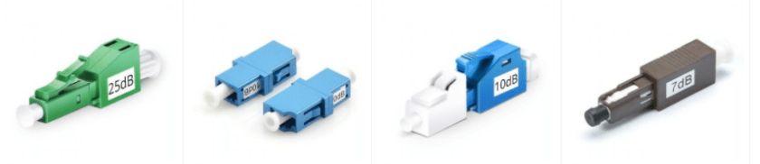
Fixed fiber optic attenuator, also called fixed plug type or fixed build-out fiber attenuator, is used in fiber optic communications to reduce the optical fiber power by a certain level. Typical attenuation values are between 1 and 30 dB. Usually, it has a male plug connector at one side to allow fiber attenuator to be plugged directly into receiver equipment or adapters in patch panel, and has female type fiber optic adapter at the other side to allow the patch cords to plug in. Fixed fiber optic attenuator name is based on the connector type and the attenuation level. LC attenuator 5dB means this attenuator uses LC fiber optic connector, and it can reduce the optical fiber power level by 5dB.

What is optical variable attenuator?
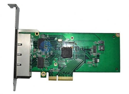
Optical variable attenuator can also be made as a plug-in card. It is a part of Fiber-Mart, all-in-one multi-service transport system. This hot-swappable plug-in variable optical attenuator is an online attenuation adjustment device, only occupying one slot in the 1U/2U/4U chassis. It is applied to applications that optical power required strict control, such as to balance signal strengths in a DWDM network system. Card optical variable attenuator adopts MEMS technology and could continually and variably reduce the light intensity in the optical network and help simulate distance or actual attenuation in the fiber optic testing work. With the card design, this optical variable attenuator is easy to install and remove without any tool. The online attenuation adjustment also contributes to safer business.

56

How to use Fiber Optic Attenuators in data link?

For a single-mode applications, especially analog CATV systems, the most important parameter, after the correct loss value, is return loss or reflectance. Many types of attenuators (especially gap loss types) suffer from high reflectance, so they can adversely affect transmitters just like highly reflective connectors.

7

Fiber Optic Attenuator in Data Link

Choose an attenuator with good reflectance specifications, and always install the attenuator ( X in the drawing) at the receiver end of the link as shown above. This is because it’s more convenient to test the receiver power before and after attenuation or while adjusting it with your power meter at the receiver, plus any reflectance will be attenuated on its path back to the source.

Test the system power with the transmitter turned on and the optical attenuator installed at the receiver, and using an optical power meter set to the system operating wavelength. Check to see whether the power is within the specified range for the receiver.

Conclusion
Fiber optic attenuator is an essential passive component in the optical communication system. With the advancement of DWDM technology, as well as the potential to flexibly upgrade the reconfigurable optical add-drop multiplexer (ROADM), the demand for optical attenuator is sure to soar, especially for optical variable attenuator. The innovation in fiber optic industry never ceases, and fiber optic attenuator will evolve to have lower cost, faster response time and enhanced integration of hybrid with other optical communication devices.Fiber-Mart provides a wide range of fiber optical attenuator.Welcome to contact with us:product@fiber-mart.com.

Some things you must know about Fusion Splicer

What is Fusion Splicer?

Fusion splicing is the act of joining two optical fibers end-to-end using heat. The goal is to fuse the two fibers together in such a way that light passing through the fibers is not scattered or reflected back by the splice, and so that the splice and the region surrounding it are almost as strong as the intact fiber.

What is Fusion Splicer?

Fusion splicing is the act of joining two optical fibers end-to-end using heat. The goal is to fuse the two fibers together in such a way that light passing through the fibers is not scattered or reflected back by the splice, and so that the splice and the region surrounding it are almost as strong as the intact fiber. The source of heat is usually an electric arc, but can also be a laser, or a gas flame, or a tungsten filament through which current is passed. and thus the splice as well as the region surrounding it are almost as strong because virgin fiber itself.

81cc

The basic fusion splicer apparatus includes two fixtures which the fibers are mounted and two electrodes. Inspection microscope assists in the placement in the prepared fiber ends into a fusion-splicing apparatus. The fibers they fit in to the apparatus, aligned, and then fused together.

Initially, fusion splicing used nichrome wire as the heating unit to melt or fuse fibers together. New fusion-splicing techniques have replaced the nichrome wire with fractional co2 lasers, electric arcs, or gas flames to heat the fiber ends, causing them to fuse together. The little size of the fusion splice along with the development of automated fusion-splicing machines make electric arc fusion the most popular splicing approaches to commercial applications.

81c

Fusion Splicing vs Mechanical Splicing

There are two types of optic fiber splicing. One is fusion splicing we mentioned above, another is mechanical splicing. In mechanical splicing two fiber optic cables are held end to end inside a sleeve using some mechanical mechanism. In this type of technique fibers aren’t joined permanently rather just accurately hold together, so that light can easily pass through from one end to another, while in fusion splicing two fibers are fused or wielded together using an electric arc, fusion splicing is most widely used technique because it provides a reliable join with lower insertions loss and practically no back reflection. Fusion splicing is generally applied on single mode fibers but in some special cases it can also be used for multi mode fibers.

The process of fusion splicing

The process of fusion splicing normally involves heat to melt or fuse the ends of two optical fibers together. The splicing process begins by preparing each fiber end for fusion.

121

1.Stripping the fiber

Stripping is the act of removing the protective polymer coating around optical fiber in preparation for fusion splicing. The splicing process begins by preparing both fiber ends for fusion, which requires that all protective coating is removed or stripped from the ends of each fiber.

2.Cleaning the fiber

The customary means to clean bare fibers is with alcohol and wipes. However, high purity isopropyl alcohol (IPA) is hygroscopic: it attracts moisture to itself. This is problematic as IPA is either procured in pre-saturated wiper format or in (host) containers ranging for USA quart to gallon to drums. From the host container the IPA is transferred to smaller more usable containers. The hydroscopic nature of IPA is such that the highest quality at 99.9% is also the most hygroscopic. This means that moisture absorption into both the host container as well as the actual user’s container begins with the time the original container is opened and continues as amounts are transferred and removed from both.

3.Cleaving the fiber

The fiber is then cleaved using the score-and-break method so that its end-face is perfectly flat and perpendicular to the axis of the fiber. The quality of each fiber end is inspected using a microscope. In fusion splicing, splice loss is a direct function of the angles and quality of the two fiber-end faces. The closer to 90 degrees the cleave angle is the lower optical loss the splice will yield. The quality of the cleave tool being used is critical.

6s

4.Splicing the fibers

Fiber spliced, still unprotected, Current fusion splicers are either core or cladding alignment. Using one of these methods the two cleaved fibers are automatically aligned by the fusion splicer[1] in the x,y,z plane, then are fused together. Prior to the removal of the spliced fiber from the fusion splicer, a proof-test is performed to ensure that the splice is strong enough to survive handling, packaging and extended use. The bare fiber area is protected either by recoating or with a splice protector. A splice protector is a heat shrinkable tube with a strength membrane and less loss.

5.Protecting the fiber

After the fibers have been successfully fused together, the bare fiber is protected either by re-applying a coating or by using a splice protector.

565

A simplified optical splicing procedure includes:

Characteristics of placement of the splicing

A simplified optical splicing procedure includes:

Characteristics of placement of the splicing process.

Checking fiber optic splice closure content and supplementary kits.

Cable installation in oval outlet.

Cable preparation.

Organization of the fibers inside the tray.

Installing the heat-shrinkable sleeve and testing it.

81

Conclusion

Fusion splicing provides permanent low-loss connections that are performed quickly and easily, which are definite advantages over competing technologies.When it comes to optical fiber fusion splicers, no other company in the world can match Fiber-MART for innovation, speed, and performance. The entire industry-leading range of splicers offers quick termination and new standards in heater shrink time. Fiber-Mart strives for even better standards each day. Like Sumitomo Type-81C Fusion Splicer, Innovation is key. It can revolutionized on-site connectivity, speed and brought lower project costs for the migration of the network. As the major leader in optical fiber and connectivity solutions, customers can expect reliability, flexibility and unbelievable performance. After all, network infrastructure expansion becomes easy when you use state-of-the-art fusion splicer solutions.Any question or need pls feel free to contact with us. E-mail: product@fiber-mart.com.


Everything you need to know about OM1 vs OM2 vs OM3 vs OM4 vs OM5

There are four commonly used OM (multimode) fibers: OM1, OM2, OM3 and OM4. Each type of them has different characteristics. The article will compare these four kinds of fibers from history,the side of core size, bandwidth, data rate, distance, color and optical source in details.

Fiber optic cable can be divided into several types. Usually we see single-mode and multimode fiber types available on the market. Multimode fibers are described by their core and cladding diameters. The diameter of the multi-mode fiber is either 50/125 µm or 62.5/125 µm. At present, there are four commonly used OM (multimode) fibers: OM1, OM2, OM3 and OM4. Each type of them has different characteristics. The article will compare these four kinds of fibers from history,the side of core size, bandwidth, data rate, distance, color and optical source in details.

1113

The picture above shows the development of OM multimode fibers. The Lime Green OM5 fibers are newly released and sure to be the mainstream transmission media in the near future.

specification of OM1, OM2, OM3 and OM4

Core Size

Multimode fiber is provided with the core diameter from 50 µm to 100 µm. Apart from OM1 with a core size of 62.5 µm, other three types are all using the 50 µm. The thick core size makes them able to carry different light waves along numerous paths without modal dispersion limitation. Nevertheless, in the long cable distance, multiple paths of light can cause signal distortion at the receiving end, resulting in an unclear and incomplete data transmission. And this is why all the types of multimode fiber can only be used for short distance.

11111

Bandwidth

Bandwidth is the bit-rate of available or consumed information capacity expressed typically in metric multiples of bits per second. The higher bandwidth is, the faster transmission speed can be. According to overfilled launch (OFL) and effective modal bandwidth (EMB) measurements, OM1 and OM2 fibers can only support OFL, but OM3 and OM4 are able to support both measurements. At the wavelengths of 850/1300 nm under OFL, the respective bandwidth of OM1, OM2, OM3, OM4 is 200/500 MHz*km, 500/500 MHz*km, 1500/500 MHz*km and 3500/500 MHz*km. And at the wavelength of 850 nm under EMB, the bandwidth of OM3 is 2000 MHz*km and OM4 even reaches 4700 MHz*km.

Data Rate

Data rate is a technical term that describes how quickly information can be exchanged between electronic devices. With a higher data rate, the transmission can be more effective. OM1 and OM2 support the Ethernet standards from 100BASE to 10GBASE with a minimum data rate of 100 Mbps and a maximum data rate of 10 Gbps. Compare with OM1 and OM2, OM3 fibers and OM4 fibers are enhanced to support much higher data rates of 40 Gbps and 100Gbps in 40G and 100G Ethernet.

55

Distance

Multimode fiber is typically used for short distance transmission. But the maximum reaches are varied in different multimode fiber types. Also, on account of different data rates, the transmitting distances are different. However, the common feature is that OM1 always supports the shortest distance yet OM4 supports the longest. For instance, based on the same data rate of 10 Gbps, the maximum reach of OM1 is 33 m, OM2 is 82 m, OM3 is 300 m and OM4 is 550 m. Thus, if a medium-sized transmission is required, OM3 and OM4 fibers are the best choices.

Color & Optical Source

The outer jacket can also be a method to distinguish OM1, OM2 from OM3, OM4. The common jacket color of OM1 and OM2 is orange, and OM3, OM4 are in aqua. In addition, OM1 and OM2 are using a light-emitting diodes (LEDs) optical source but OM3 and OM4 adopt the vertical-cavity surface-emitting laser (VCSELs) optical source.

44

color and optical source of OM1, OM2, OM3 and OM4

Application

OM1 fibers and OM2 fibers are widely employed for short-haul networks, local area networks (LANs) and private networks. OM3 is applied to a larger private networks. Different from the previous multimode types, OM4 is more advanced to be used for high-speed networks in data centers, financial centers and corporate campuses.

Conclusion

It is very important to choose the right fiber type for your application. Future-proofing network design is crucial for network planning, but there is often a cost for that speed. With a higher performance, OM3 fibers and OM4 fibers are definitely more expensive than OM1 and OM2 fibers . So plan well and spend wisely.

How much do you know about the RJ45 interface?

As we all know, cables can transmit information along their length. To actually get the information where it needs to go, you need to make the right connections to an RJ45 connector. Your cable run needs to terminate into a connector, which needs a jack to plug into. RJ45 is a standard type of connector for network cables, which is usually used for data transmission. RJ45 connectors are most common applications for Ethernet cables and networks.

As we all know, cables can transmit information along their length. To actually get the information where it needs to go, you need to make the right connections to an RJ45 connector. Your cable run needs to terminate into a connector, which needs a jack to plug into. RJ45 is a standard type of connector for network cables, which is usually used for data transmission. RJ45 connectors are most common applications for Ethernet cables and networks.

The RJ45 connector is a modular plug used primarily for network cabling. The connector feature eight pins to which the wire strands of a cable interface electrically. Standard RJ-45 pinouts define the arrangement of the individual wires needed when attaching connectors to a cable.

4545

RJ45 is a type of a variety of different connectors (for example: a type of RJ11 is also a connector, but it is used in the phone). The line using of RJ45 connector has two types: straight-through and cross-over.Have you ever had some confusion about RJ45 interface? That’s what we’ll explore today

Introduction of RJ45 Connector

RJ45 connector is the most common twisted-pair connector for Ethernet cables and networks. “RJ” means “registered jack”, which is a standardized telecommunication network interface for connecting voice and data equipment to a service provided by a local exchange carrier or long distance carrier. The physical connectors that registered jacks use are mainly the modular connector and 50-pin miniature ribbon connector types. RJ45 connector is an 8-position, 8-contact (8P8C) modular plug and jack, which is commonly used to connect computers onto Ethernet-based local area networks (LAN). RJ45 cable plug is usually made of a plastic piece with eight pins on the port. Four of the pins are used for sending and receiving data, and the other four are used for other technologies or power networking devices.

6645

Introduction of RJ45 Connector Color Code

As we all know, there are two wiring schemes: T568A and T568B, which are used to terminate the twisted-pair cable onto the connector interface. Two standards define how the RJ45 pinouts to arrange the individual eight wires when linking RJ45 connector to a cable. These wiring layouts have their own color convention, and following the convention is important to ensure electrical compatibility.

RJ45 Connector VS. RJ11 Connector

Several other types of connectors closely resemble RJ45, and the RJ11 connector used with telephone cables is one of such connectors. The close physical similarity of RJ45 and RJ11 makes it difficult for an untrained eye to tell the two apart. RJ11 connector is a 6P2C (6 position 2 contact) modular connector – only uses six positions rather than eight positions, which make them less popular than RJ45 connectors.

RJ45 and RJ11 are two commonly used jacks, each with their own specific purpose. The biggest difference between them is that they are used for different applications. RJ45 is used in networking, where you connect computers or other network elements to each other. RJ11 is the cable connector that is being used in telephone sets.

45

Aside from the application, another difference is the number of wires in their connectors. If you look closely at both connectors, you would see that there are only four wires inside an RJ11 while there are eight wires inside an RJ45. As a consequence, RJ45 connector is a little bit bigger than RJ11. It is then quite easy to deduce that you cannot plug in an RJ45 connector to a RJ11 slot but the opposite is possible. Although the smaller size of RJ11 makes it easier to be plugged into the RJ45 slot, it is not recommended to do so since this may damage the device that adopts the RJ45 slot. With proper knowledge and training, some people have been able to use RJ45s all over their house instead of RJ11s.

At present, RJ45 jacks are usually placed on the wall outlets inside people’s houses to reduce the number of visible wiring when using VoIP handsets that are rapidly gaining popularity.

RJ45 type network interface

10/100 Base TX RJ45 interface is commonly used in Ethernet interface, support for network connection speed of 10Base and 100Base of adaptive common RJ45 connector into two categories: for Ethernet cards, routers and Ethernet interface DTE type, for switches DCE type. DTE can be called data terminal equipment; the DCE can be called data communications equipment. In one sense, the DTE device is called the “active communications equipment DCE device called a” passive communications equipment. When the two types of devices use RJ45 interface communication, you must use a crossover cable. This can be defined from the following types of pin definitions of the RJ45 the DTE and RJ45 DCE type pin.

 RJ45 type cable plug

The RJ45 network cable connector also known as crystal head which a total of eight cores made of, widely used in LAN and ADSL broadband Internet connection to the user’s cable network equipment which named as CAT cables or twisted-pair. In the specific application, the RJ45-type plugs and cables, there are two connection methods, respectively called T568A line sequence and T568B linear order.

45454545

Application in products

RJ45 ports are available on fiber optical products like media converters, pci-e cards, PDH multiplexers, protocol converters, Patch panels, and so on.

Conclusion

RJ45 connectors are the key part of Ethernet connectivity to transmit voice and data media. They were developed as much smaller and cheaper replacements to the older telephone installation methods of hardwired cords. The easy plug-n-play style reduces the difficulty of installation. Compared with RJ11, RJ45 is suitable for more applications, such as Ethernet networking, telecommunications, factory automation and so on. It is frequently used for networking devices including Ethernet cables, modems, computers, laptops, printers, etc.


Introduction of Fiber Optic Pigtail

Fiber optic pigtail offers an optimal way to joint optical fiber, which is used in 99% of single-mode applications.

We know the way that cables are attached to the system is quite essential to the performance of the telecommunication network. Joining optical fibers with a fiber optic pigtail is proven and considered to be an effective way to ease fiber termination. As the cable is connected properly, it enables optical signals to pass with little return loss and low attenuation. Fiber optic pigtail offers an optimal way to joint optical fiber, which is used in 99% of single-mode applications.

etet

  1. What is Fiber Optic Pigtail ?

Fiber optic pigtail is a fiber cable end with fiber optic connectors at only either side of the cable while leaving sleep issues no connectors, so the connector side could be from the equipment and the other part can be melted with optical cable fibers.

Fiber optic pigtails are utilized to achieve accurate mounting for precision alignment of fiber optical components. They’re usually used with fiber optic management equipment like ODF, splice closures and cross cabinets.

tr

A fiber pigtail is really a single, short, usually unbuffered, optical fiber which has an optical connector pre-installed on one end along with a period of exposed fiber in the other end. The end of the pigtail is stripped and fusion spliced to a single fiber of a multi-fiber trunk. Splicing of pigtails to each fiber within the trunk “breaks out” the multi-fiber cable into its component fibers for connection to the end equipment.

Fiber pigtails can have female or male connectors. Female connectors might be mounted in a patch panel, often in pairs although single-fiber solutions exist, to allow them to be connected to endpoints or other fiber runs with patch fibers. Alternatively they can have male connectors and plug directly into an optical transceiver.

trt

2. Fiber Optic Pigtail Types

Fiber optic pigtails are available in various types: Grouped by pigtail connector type, there are LC fiber optic pigtails, SC fiber pigtails and ST fiber pigtails, etc. By fiber type, there are single-mode fiber optic pigtail and multimode fiber optic pigtail. And by fiber count, 6 fibers, 12 fibers optic pigtails can be found in the market.

  • By Fiber Type

Fiber optic pigtails can be divided into single-mode (colored yellow) and multimode (colored orange) fiber. Multimode fiber optic pigtails use 62.5/125 micron or 50/125 micron bulk multimode fiber cables and terminated them with multimode fiber optic connectors at one end. 10G multimode fiber cables (OM3 or OM4) are also available in fiber optic pigtails. The jacket color of 10G OM3 and OM4 fiber optic pigtail is usually aqua. Single-mode fiber pigtail cables use 9/125 micron single-mode fiber cable and terminated with single-mode fiber connectors at one end.

  • By Connector Type

According to different types of pigtail cable connector terminated at the end, there are LC fiber pigtail, SC fiber pigtail, ST fiber pigtail, FC fiber pigtail, MT-RJ fiber pigtail, E2000 fiber pigtail and so on. With different structures and appearance, each of them has their own advantages in different applications and systems. Let’s go through some widely used ones.

SC Fiber Optic Pigtail: SC pigtail cable connector is a non-optical disconnect connector with a 2.5mm pre-radiused zirconia or stainless alloy ferrule. SC fiber pigtail is economical for use in applications such as CATV, LAN, WAN, test and measurement.

FC Fiber Optic Pigtail: FC fiber pigtail takes the advantage of the metallic body of FC optical connectors, featuring the screw type structure and high precision ceramic ferrules. FC fiber optic pigtails and its related products are widely applied for the general applications.

ST Fiber Optic Pigtail: ST pigtail connector is the most popular connector for multimode fiber optic LAN applications. It has a long 2.5mm diameter ferrule made of ceramic (zirconia), stainless alloy or plastic. Hence SC fiber pigtails are commonly seen in telecommunications, industry, medical and sensor fields.

Like fiber optic patch cords, fiber optic pigtails can be divided into UPC and APC versions. Most commonly used types are SC/APC pigtail, FC/APC pigtail and MU/UPC pigtail.

  • By Application Environment

Some pigtail cables are specially installed to withstand the harsh or extreme environments, so here comes armored fiber pigtail and waterproof fiber pigtail.

Armored Pigtail: enclosed with stainless steel tube or other strong steel inside the outer jacket, armored fiber optic pigtails provide extra protection for the fiber inside and added reliability for the network, while reduce the unnecessary damage caused by rodents, construction work, weight of other cables.

Waterproof Pigtail: designed with a stainless steel strengthened waterproof unit and armored outdoor PE (Poly Ethylene) jacket, waterproof fiber pigtail is a great fit in harsh environments, like communication towers, CATV and military. Waterproof pigtail cable boosts good toughness, tensile and reliable performance, facilitating the use in outdoor connections.

  • By Fiber Count

Fiber optic pigtails could have 1, 2, 4, 6, 8, 12, 24 and 48 strand fiber counts. Simplex fiber optic pigtail has one fiber and a connector on one end. Duplex fiber optic pigtail has two fibers and two connectors on one end. Each fiber is marked “A” or “B” or different colored connector boots are used to mark polarity. Similarly, 4, 6, 8, 12, 24, 48 and more than 48 fibers fiber optic pigtails have their corresponding feature.

Note: Fiber pigtails have female or male connectors. Female connectors could be mounted in a patch panel. And they also have male connectors that plugged directly into an optical transceiver.

e

3. How to Select Quality Fiber Pigtails?

Fiber optic pigtails are attached to cables by fusion or mechanical splicing, both of which provide a fast termination method. Basically, fiber pigtail assemblies are cable assemblies, which means the parts contained in fiber pigtail—a connector, a ferrule, standard fiber and jacket types, are components that every experienced fiber technician is familiar with. Notice that always ordering fiber pigtails a few feet more than you think you`ll need. The extra slack allows for splicing errors to be corrected, or you may have to start with another fiber pigtail. Saving More Labour Cost and Time, One of the benefits of fiber optic pigtail is lower labor costs: given the access to a fusion splicer, you just splice the fiber pigtail cable right onto the cable in a minute or less.

The quality of fiber optic pigtail is typically high because the connectorized end is attached in a controlled environment–the factory. And the factory can make single-mode pigtail assembly more accurately than a field termination can be done. Testing a fiber pigtail in the field is not easy, but in the factory, you are dealing with credible measurements. Which on the other hand saves much time spent on field termination.

4. Conclusion

Fiber optic pigtail serves as a feasible and reliable solution for easier fiber termination, which effectively contribute to save plenty of operating time and labour cost. The performance of fiber pigtail matters a lot, so the quality of connector, ferrule material as well as cable length of pigtails should be considered to ensure easier fiber termination.

Introduction of Fiber Optic Patch Panel

What Is & How Many Types & How To Use a Fiber Optic Patch Panel?

What Is Fiber Optic Patch Panel?

First, we need to know, Fiber optic patch panel also called ODF (optical distribution frame), some people like to call as this. it is designed for fiber optic communications center room to develop fiber optic wiring devices, cable fixing and protection features fiber optic cable end of contract function, line control function, fiber optic cable core, and fiber optic pigtail protection function. In simple terms, fiber optic patch panel’s function is to terminate the fiber optic cable and provide access to the cable’s individual fibers for cross connection.

A basic fiber optic panel is typically made up of a metal frame that encloses the adapter panels, the connector coupler and a splice tray. The fiber optic cables connect to the panels through the coupler. One side of the panel is usually fixed, meaning the cables aren’t disconnected at any point. The other side of the panel is reserved for cables that can be connected and disconnected to arrange the wire circuits as needed. The splice tray allows cables to be neatly arranged in the fiber optic panel.

--

How Many Types of Fiber Patch Panel?

Fiber patch panel is available in two versions: rack mount patch panel and wall mount patch panel. Both can house, organize, manage and protect fiber optic cable, splices and connectors.

QQ

1. Rack Mount Fiber Patch Panel

Rack mount patch panel is generally made for standard 19 inch rack mounting. Depending on the number of connections required, it is often available in 1U, 2U, 4U configurations with flat or angled design. One could choose the most proper one depending on the space and requirements of your project.

 2. Wall Mount Fiber Patch Panel

Wall mount fiber patch panel is featured with low-profile, compact design, offering an optimal choice for securing and protecting fiber connections in telecommunications closets or other installation areas where wall space is a premium. Further more, it enables clear and intuitive cable routing paths for integrated bend radius protections and can be easily mounted to any wall using the internal mounting holes.

444

How To Use a Fiber Optic Patch Panel?

Fiber optic patch panels are commonly used in fiber optic management unit. When you install and manage the fiber optic links, you may encounter hundreds or even thousands of fiber optic cables and cable connections. Getting a fiber optic patch panel is mainly for two reasons: termination and better cable management. As for patch panel termination, it is the step to terminate fibers on the patch panel, a precise task required much attention.

As for cable management, here I recommend you to accompany it with cable managers. From a top-down perspective, the order of the devices in a cabinet should be: fiber patch panel 1, cable manager 1, fiber patch panel 2, cable manager 2

For fiber optic cabling cable management, you should plan the location of your fiber connectivity hardware carefully, including fiber patch panels. You can choose between direct cross connection and patch panel. It is also necessary to arrange your routing and dressing of your fiber patch cords if you choose to use fiber panels. In the meantime, you also have a choice to use fiber cable management brackets to avoid the dangling fiber patch cables. Owning a fiber optic path will not only spare you a lot of time and energy in cabling design, but also present you a neat cabling system, which will bring you efficient work.

4444

Conclusion

For modern data center, it is imperative to stay organized with fiber optic patch panel – not just for easy upgrades and quick access, but also to prevent dangers that are inherent with any network system. Fiber optic patch panel is a kind of important supplementary equipment in the optical transmission system, mainly used for the cable end of contract of the optical fiber blend splicing, the optical connector is mounted, the optical path adjusting pick excess pigtail storage and protection of the cable, which for the safe operation of the optical fiber communication network and the flexibility people plays an important role.Fiber-Mart can supply many kinds fiber optic patch panel . If you have any questions or requirement of fiber optic patch panel,welcome to contact us.